that we emplaced. The resulting reflections required a
One-hundred-MHz data were also acquired but are not
large amount of gain (up to 65 dB) at time ranges of
discussed because the direct coupling between these
only 50 (300 MHz) and 30 ns (600 MHz). The short
antennas, which lasts approximately 3050 ns, obliter-
time ranges were sufficient to capture target responses
ated any near-surface returns. The antenna directivity
throughout the site but were also necessary to limit back-
becomes increasingly confined beneath the antenna as
ε′ increases (Arcone 1995). The typical shape of a trans-
ground radiowave interference, which beat with the
radar returns at the high-gain time ranges. The high gain
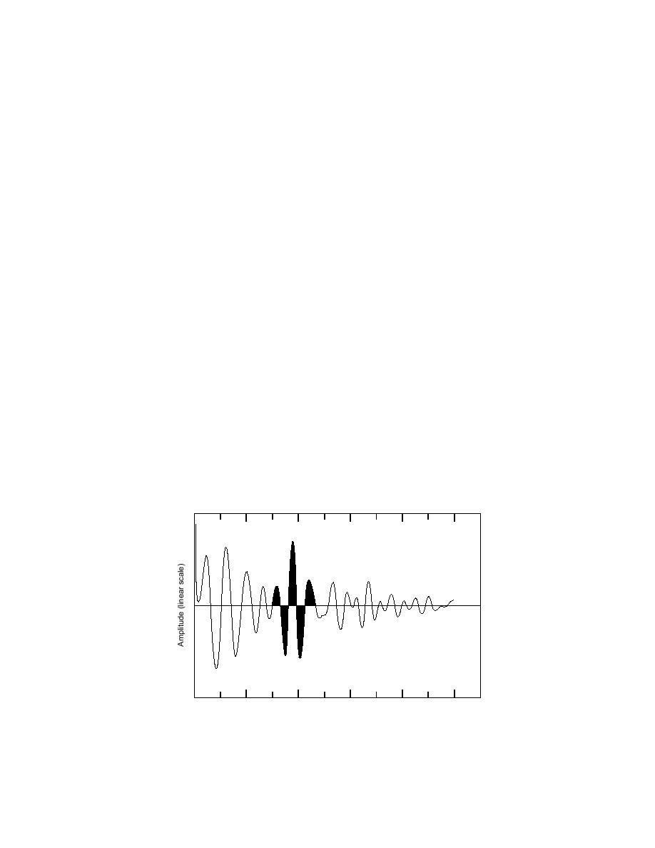
mitted GPR wavelet for either the 300- or 600-MHz
had the negative effect of amplifying small antenna
antenna system is shown in Figure 2. The phase polar-
impedance mismatches and low-amplitude clutter (un-
ity sequence of the half-cycles defines the wavelet phase
wanted events), which probably originated from radia-
(Arcone 1995).
tion that leaked onto the antenna housing and cables.
Field profiling
These events usually arrive at constant time delay and
their interference can be alleviated with a horizontal
We profiled along established transects and entered
"background removal" filter. However, in our case,
electronic event markers on the profiles at previously
where short time ranges were used, electronic jitter and
established, 100-ft (30-m) distance marks. The transects
erratic movement of the antenna may have caused these
generally deviated from a straight line by 12 m, and
events to arrive at variable amplitude and so their
sometimes by as much as 5 m to avoid isolated bushes,
interference was not consistently reduced by filtering.
trees, and severe ruts. Consequently we cannot recon-
All antennas were resistively loaded dipoles. The
struct our exact position along the lines, and errors of
smaller, 300- and 600-MHz antennas are shielded with
as much as 20 ft (6 m) may occur in our interpretation
semi-cylindrical housings to alleviate above-surface
of distance between markers. We dragged all our
clutter. These frequencies are "local" (also known as
antennas by vehicle at less than 1 m/s for long distances
"instantaneous") values, which correspond with the
and by hand for the small surveys over emplaced tar-
dominant periods and lie approximately at the center
gets. All antennas were polarized perpendicular to the
of the received wavelet spectrum. They are consider-
transect direction. We determined that vehicle reflec-
ably below the manufacturer's specifications for these
tions were not in the data by comparing profiles
antennas (400 and 900 MHz, respectively), which
recorded with and without the vehicle. We placed the
generally apply to operation in air or on the ground with
smaller antennas in a fiberglass box to alleviate erratic
lower values of dielectric permittivity and loss than
antenna-to-ground coupling. However, the uneven tow-
encountered here. Their transmitters do not exceed 8
ing speed over the rough ground also degraded the
W (peak power) in order to protect the nearby receiver.
appearance of the profiles.
0
10
20
30
40
50
Time (ns)
Figure 2. Typical form of a radiated GPR wavelet (darkened area).
The frequency characterization of the wavelet refers to the inverse
of the dominant wavelet period (in this case, about 300 MHz).
4


 Previous Page
