Construction
Design
The gallery was constructed by excavating an
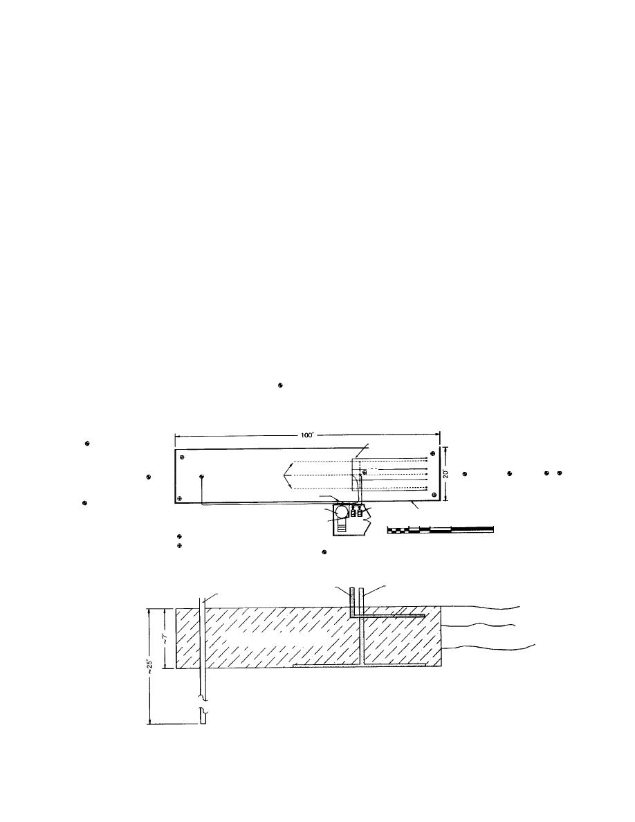
Design views of the infiltration gallery, pump-
area 25 by 100 ft, 67 ft deep (7.5 by 30 m, about 2
ing well, and piping systems are shown in Figure
m deep). High groundwater was encountered
6. To promote infiltration of water through the
during excavation, limiting the depth of excava-
sides and bottom of the gallery, it is filled with 2
tion. Material removed during the excavation was
5 in. (513 cm) cobbles and a low percentage of
suspected of having been contaminated by the
finer materials. The pumping well is designed to
prior fuel spill and was placed directly into the
draw water from a depth of 1520 ft (56 m)
landfarm. Following excavation, approximately
below the original ground surface and to pro-
1 ft (30 cm) of the 25 in. (513 cm) infiltration
duce 3545 gal/min (133170 L/min) of flow.
rock was placed on the bottom of the gallery. The
This water is distributed in the infiltration gal-
aeration manifold was then positioned and infil-
lery through the system of 4-in. (10-cm) perfo-
tration rock added to 1 ft (30 cm) below the final
rated pipes located 1 ft (30 cm) below the surface
grade of the structure. The water distribution
of the infiltration rock. Nutrients are mixed in a
piping was then placed and infiltration rock
500-gal (1893-L) tank located in the equipment
added to achieve the final design grade. A 1-ft
shed next to the gallery. The nutrient solution is
injected into the pumped water stream prior to
(30-cm) berm was placed around the gallery to
prevent surface runoff from carrying fines into
infiltration using a chemical feed pump. Oxygen
the infiltration rock. When the gallery was com-
is added to the water in the infiltration gallery
pleted, the pumping well was installed and the
by 4-in. (10-cm) perforated pipe located near
equipment shelter housing the fertilizer mix tank,
the bottom of the gallery. Air is supplied to the
aeration piping by two 10-hp (100-kg cal/min)
blowers, and electrical distribution panel was
installed on site.
blowers.
B3
DEC2
INFILTRATION PIPING
IG4
IG8
TR2 TR1
TR3
IG3
IG1
IGWW
IG6
AERATION PIPING
IG7
DEC1
WATER FLOW METER
IG5
BLOWERS
MIX TANK
GALLERY BOUNDARY
FERTILIZER FEED PUMP
4'
8'
8'
0
16'
32'
MONITORING WELL
MONITORING POINT
IG2
AERATION PIPING
INFILTRATION PIPING
PUMPING WELL
POROUS BACKFILL
INFILTRATION GALLERY
SECTION (NOT TO SCALE)
Figure 6. Infiltration gallery and monitoring wells (1 ft = 0.3048 m).
12


 Previous Page
