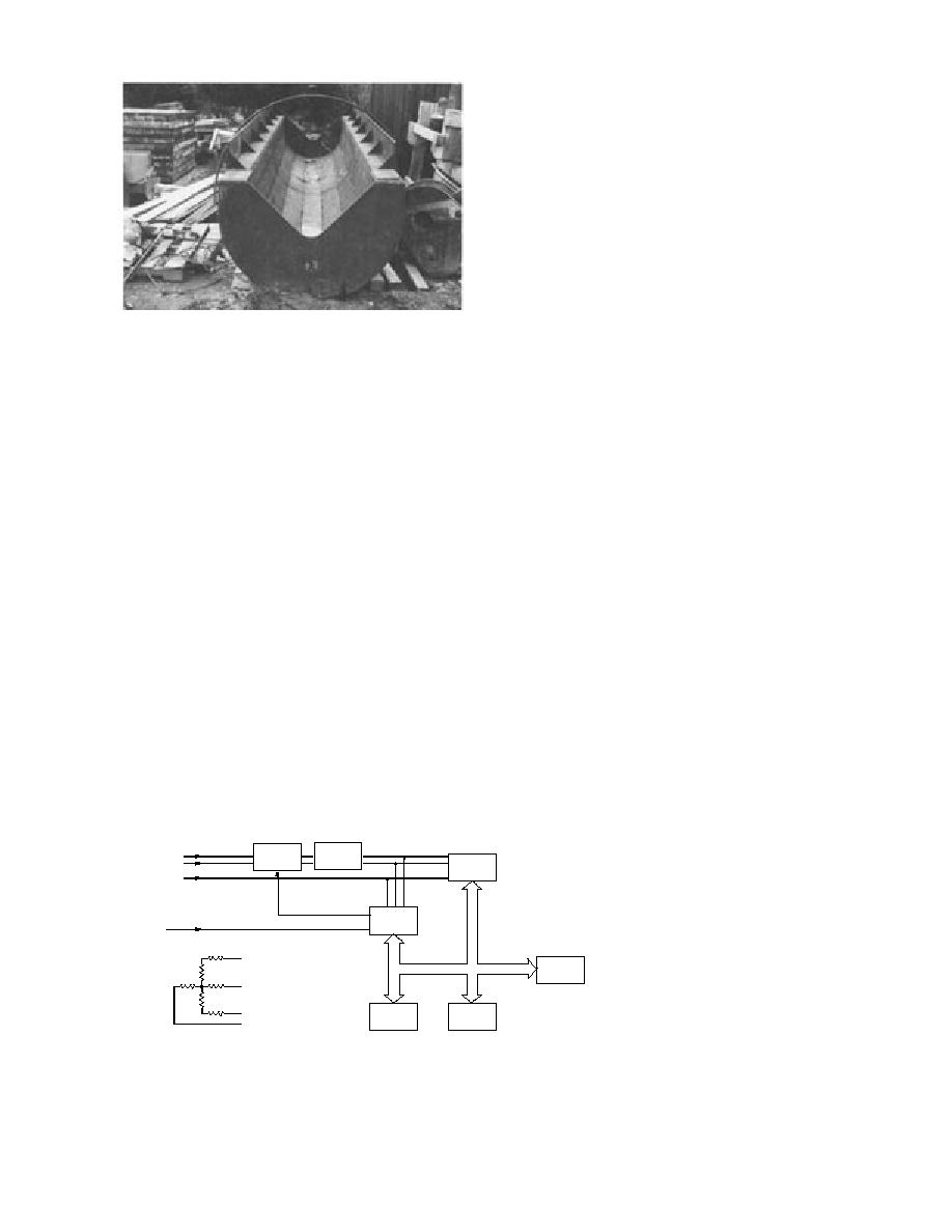
cess ports for the conduits are on the four sides
of the pier at both the mud line and the outer
edge of the riprap.
Ice force data acquisition systems
The ice force instruments mounted on the pier
are linked to the onshore data acquisition system
(DAS) via a 25-shielded-pair instrumentation trunk
cable. Instruments on the pier connect to the trunk
cable via screw terminal strips housed with a
weatherproof box above the pier.
For the first year of operation (1991-92) an analog
tape recorder was used to capture the output of
both load channels and the water level pressure
Figure 9. Inner surface of the load beam.
transducer. Data recording was triggered when
the measured load exceeded a preset threshold.
Once triggered, analog signals were recorded until
Our approach will be to install the transducer in
the load signal fell below the threshold for more
an instrumentation conduit at the edge of the
than 5 minutes. In a continuous record mode, a
riprap just upstream of the pier. For protection
single tape would last 12 hours. The recorded
from floating debris the instrumentation wires
analog data were later digitized for analysis.
will be pulled through a conduit cast in the pier
For the 1992-93 season a computer-based DAS
(Fig. 8).
was installed to monitor the instrumentation in
Real-time measurement of the ice thickness
real time (Fig. 10). The controlling software per-
using impulse radar technology is being devel-
formed three functions: steady-state measure-
oped at CRREL (Yankielun 1992). The advantage
ments, dynamic measurements and equipment
of this approach is that both the transmitter and
health monitoring. In steady-state conditions, the
the receiver can be located on the bridge super-
ice is stationary and the objective was to docu-
structure, thus avoiding damage from moving
ment the interaction between water level, air tem-
ice and floating debris. As this new technology is
perature and ice load. To reduce random error,
developed, it will be incorporated into the in-
each scan was the average of five readings. If the
strumentation package at the White River site
load or water level changed by a preset margin
for evaluation and will eventually replace the
or at default-time increments, the scan was re-
sonarultrasonic system.
corded.
Instrumentation conduits have been incorpo-
In the dynamic mode the ice is moving and
rated into the pier to facilitate easy installation
impacting the structure. Dynamic interaction was
and evaluation of future instrumentation for moni-
detected when the output voltage exceeded a
toring ice jams and the bed erosion between the
threshold. To avoid the limited frequency response
piers. For complete flexibility in locating any of
of the A/D converter in the HP 3421 data proces-
the future bottom-founded instrumentation, ac-
sor, signals were captured on an
analog tape recorder. Recording
Load Cell
Vishay
the analog data provided the op-
Short
Amplifier
Tape
Shunt
Star Bridge
tion of digitizing the breakup data
Recorder
Water Level
with appropriate fast-rise-time
10-V
equipment or signal processors
Power Supply
Digital I/O
HP 3421
or both. To capture intermittent
Air
A/D
Temperature
impacts, the tape recorder would
record until the output voltage
HP 9836
HP-IB Bus
Computer
fell below the dynamic threshold
for more than 5 minutes.
Disc
Printer
Several features were incorpo-
Drive
Star Bridge
rated into the data collection sys-
Figure 10. Data acquisition system used for monitoring the ice force tem to document the system's
instruments.
performance. Sources of potential
7


 Previous Page
