The proposed CASPPR allow a certain amount
icebreaker Ymer in 1933. Although this system is
of plastic deformation of the structure under ex-
still being used on many icebreakers, new me-
treme ice loads, and they provide factors to account
chanical and electrical transmissions have been in-
for the post-yield buckling of stiffened structures.
troduced on newer icebreakers and icebreaking
DesRochers et al. (1994) compared the stability of
cargo ships. Since 1966, the number of ships with
flat bars with that of angle sections in a stiffened
controllable-pitch propellers and mechanical trans-
structure. When a structure is designed for buck-
missions is steadily increasing. The Russian LASH
ling according to linear analysis, flat bars are
vessel Sevmorput, delivered in 1986, placed all of
avoided because angle sections have large mo-
its propulsion power on one shaft using a control-
ments of inertia to resist bending. However,
lable-pitch propeller and mechanical transmission,
DesRochers et al. (1994) found that the use of flat
thus doubling the power transmitted per shaft
bar sections increased the stability of the compos-
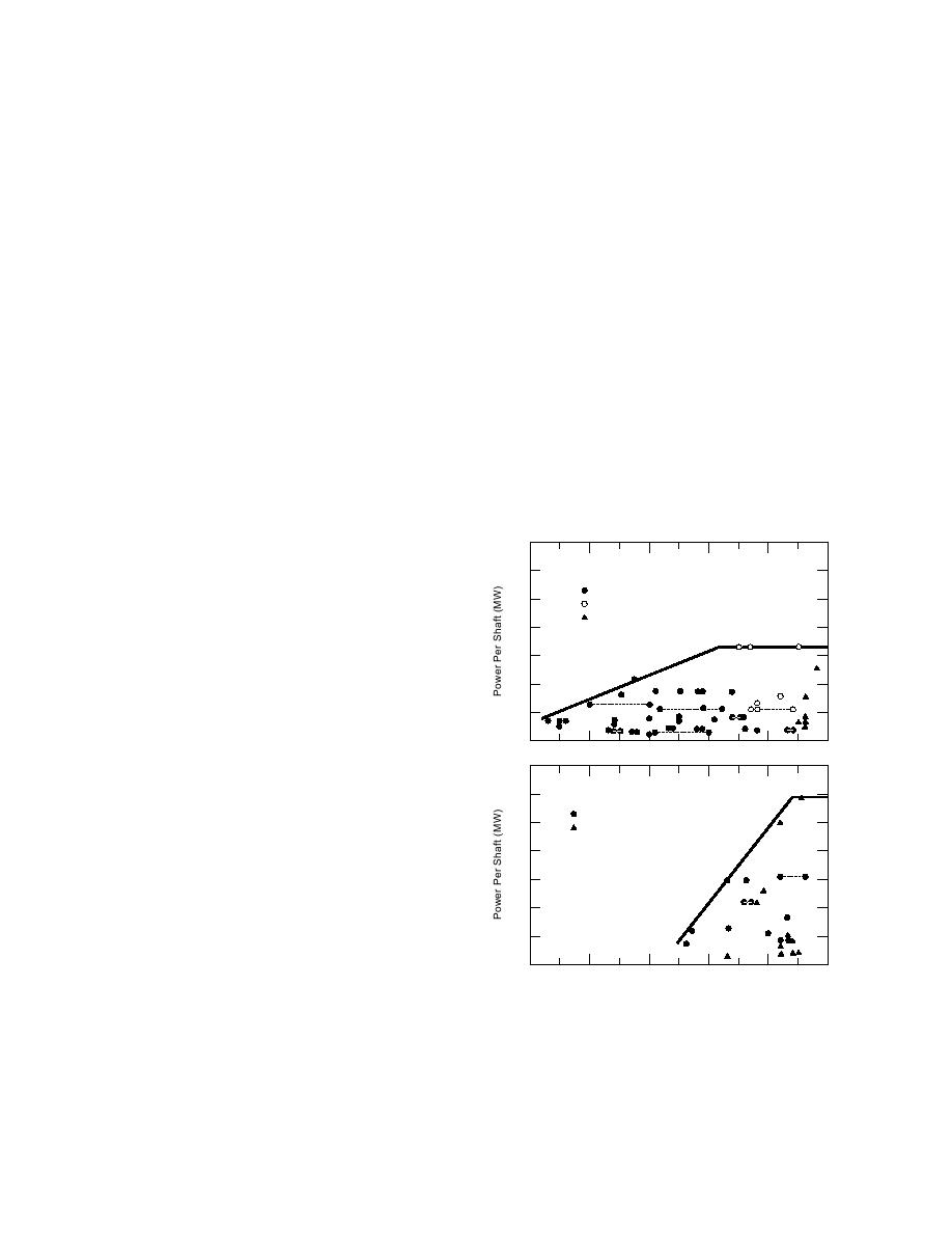
from 16.65 to 29.42 MW (Fig. 15b).
ite structure beyond the yield point of the mate-
One of the main reasons to use direct mechani-
rial, whereas the structural stability decreased with
cal transmission is to cut down the losses in trans-
the use of angle sections as yielding progressed
mission. Since 1978, propeller nozzles have been
through the frame. The structure of the Canadian
fitted to icebreakers to increase thrust and to pre-
icebreaking cargo ship Arctic has been redesigned
vent propeller damage by reducing ice ingestion.
according to CASPPR to carry full ice loads with-
Nozzles have been installed on most of the Beau-
out failure.
fort Sea ice managementsupply vessels, whereas
The Swedish icebreaker Oden is the first ice-
Polar Sea and Polar Star have operated in ice with-
breaker designed according to the technology be-
out nozzles since 1976. Recently, azimuth-mount-
hind the proposed CASPPR, making it possible to
ed propulsion units have been installed on the
use a large frame spacing of 850 mm instead of the
Finnish icebreakers Finnica and Nordica and it is
normal 400 mm (Johansson et al. 1994). This has
resulted in considerable cost savings in construc-
35
tion. After the voyage of Oden to the North Pole,
a
inspection of the structural damage revealed some
30
Electrical Transmission
indents in the shell plating between frame stations
DC-DC
25
AC-DC
30 and 76 on both sides, and some deformation in
AC-AC
the side and bottom frames (flange, web and
20
bracket), but this damage was not serious. The
15
damaged frames were reinforced, but the indents
in the steel plates were left as they were (Backman
10
1994).
13
3
6
5
2
4
3
3
15
2
0
PROPULSION SYSTEM
35
b
30
The major components of the propulsion sys-
Mechanical Transmission
tem of an icebreaking vessel, or any ship, are the
CPP
25
CPP in Nozzle
propellers, shafts, transmission systems and prime
movers. The number of propellers varies between
20
one and three. Developments in propulsion sys-
19
15
tems that have taken place during the last four to
five decades are reflected in those of existing ice-
10
4
breakers and icebreaking cargo ships, and these
2
5
become apparent in the plot of shaft power vs. the
0
year of construction (Fig. 15). Some of the special
1940
1950
1960
1970
1980
1990
features of propulsion systems, such as control-
Year of Construction
lable-pitch propellers and mechanical transmis-
sions, nozzles and various electrical transmissions,
Figure 15. Shaft power vs. year of construction for
have been highlighted in Figure 15.
icebreaking ships: (a) electrical transmission system, and
The dcdc electrical transmission has been com-
(b) mechanical transmission system (after Dick and
monly used since its introduction on the Swedish
Laframboise 1989).
15


 Previous Page
