high rates of indentation, resulting in nonsimul-
tures. The fracture toughness of steel depends on
taneous contact between the ice and the indentor.
the operating temperature and on the rate of load-
Design values are taken from empirical relations
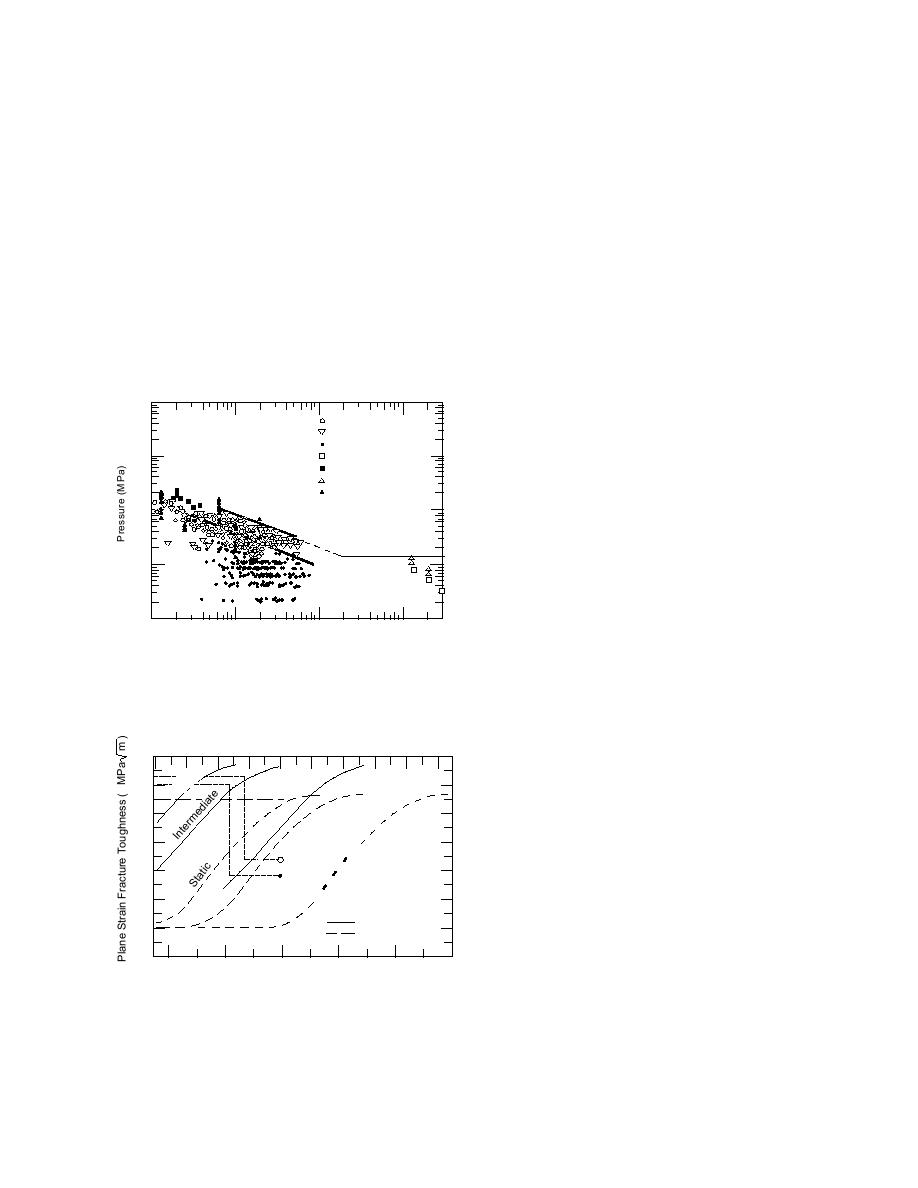
ing. In Figure 13, the plane strain fracture tough-
obtained from full-scale measurements of ice pres-
ness of two types of steel has been plotted with
sure. The data on effective pressures obtained from
respect to temperature for three rates of loading.
full-scale measurements during iceship and ice
Steel fractures in a brittle manner, without any
structure interactions (Masterson and Frederking
warning of impending failure, when the stresses
are of sufficient magnitude to propagate a crack
1993) are plotted with respect to contact area in
from a flaw or small crack in the material. The cri-
Figure 12, and these data provide empirical val-
terion for crack propagation in linear elastic frac-
ues for effective pressure to be used in design.
ture mechanics is that an existing crack will grow
when the stress intensity factor at the crack tip is
Materials
greater than the fracture toughness of the mate-
Considerable effort has been devoted by classi-
rial. For nonlinear material behavior, the causes
fication societies and regulatory authorities to the
for brittle fracture have now been established, and
selection of steel grades suitable for use in the struc-
the relationships among the cause of fracture, the
ture of ships that are exposed to very low tempera-
toughness of the material, the flaw size and shape,
the loading rate of the structure, and the tempera-
1000
ture are understood. From this understanding,
3 m2 Pond Inlet
materials and welding techniques have been de-
M.V. Arctic
veloped to increase the reliability of ship structures.
Kigoriak
100
Hans Is. ('83)
It is the consensus of many operators that the steel
Hobson's Choice ('89)
used in the present generation of polar ships is
Molikpaq (May '89)
Flat Jack
mostly adequate (Dick et al. 1987).
0.572
p = 8.1A
10
There are currently two procedures for specify-
ing the type of steel to be used in different parts of
a ship: "design by rule" and "design by analysis."
Mean
1.0
Design-by-rule procedures require the designer to
consider service temperature and to select steel
grades that have adequate notch toughness. De-
0.1
sign-by-analysis procedures require the designer
0.1
1.0
10
100
300
Area (m 2 )
to consider the magnitude and the rate of loading
that may be applied during the life of a compo-
Figure 12. Measured effective pressure vs. contact area
nent, and to design that component with adequate
(after Masterson and Frederking 1993).
reliability according to its importance. The design-
by-analysis approach places a large responsibility
on the designer, but it may provide a more reliable
Temperature (F)
and economical design than that by the design-
200 160 120 80 40
0
40
80
120
160
140
by-rule approach.
act
tic
Imp
ta
The midbody region of a ship will experience
120
S
ct
te
vibrations excited by shocks at the bow, but the
pa
dia
me
Im
100
vibratory stresses have much longer rise time than
ter
In
shock-induced stresses, resulting in small chances
80
Longitudinal
of initiating a fracture. However, the static stresses
Requirements
60
from vibrations may be high enough to cause frac-
Transverse
ture in the primary structure of a ship. Ships have
Requirements
40
experienced brittle fracture in the midbody region,
Grade 'EH' Steel
and because damage in this area is potentially more
20
Grade 'A'
catastrophic than damage to the bow, materials and
0
welding techniques should prevent both crack ini-
120
80
40
0
40
80
Temperature (C)
tiation and propagation. Because small cracks and
Figure 13. Plane strain fracture toughness vs. tempera-
defects in a material are inevitable, the material
ture for two grades of steel ("A" and "EH") (after Dick
selected must have crack arrest properties to stop
et al. 1987).
crack propagation.
13


 Previous Page
