23
DESIGN OF ICE BOOMS
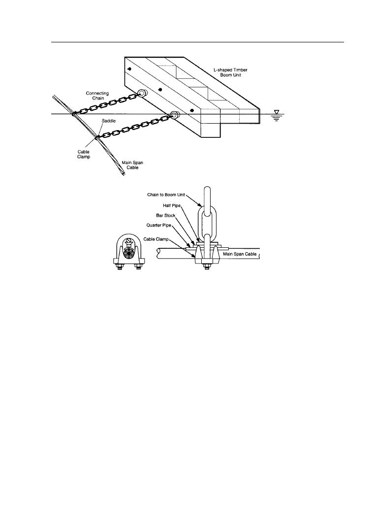
12. Triple timber ice
boom unit, showing
connections to main
cable.
13. Fabricated steel
saddles, designed to pro-
tect the main wire rope
from pinching by the
cable clamps.
section steel pipe booms on the lower St. Lawrence River (Fig.
11d). Plastic tubing has also been used (Fig. 11e). For additional
examples of possible boom cross-sectional geometries, refer to
the Ice Engineering (U.S. Army Corps of Engineers 1982).
Boom unit
The boom unit is generally connected to the main load carrying
connections
cable by a 3- to 5-ft (0.9- to 1.5-m) length of chain or wire rope
(Fig. 12). The location of the chain-to-boom-unit connection af-
fects the righting moment, but structural considerations are equally
important. The boom unit connector chains attach to cable clamps
on the main span cable. Special steel saddles must be fabricated to
protect the main wire rope from being pinched by the cable clamps
(Fig.13). Figure 14 shows standard fittings useful in the design of
ice boom connections. Included are open and closed spelter sock-
ets used to link wire rope to various fittings such as shackles,
chains, and connector plates.
Failure
If one boom component fails, the load on adjacent components
considerations
will increase substantially. A failure analysis should therefore be
made on the multicomponent structure to examine the effect on
adjacent members, should one member fail. Fuse-links, or spe-


 Previous Page
