21
DESIGN OF ICE BOOMS
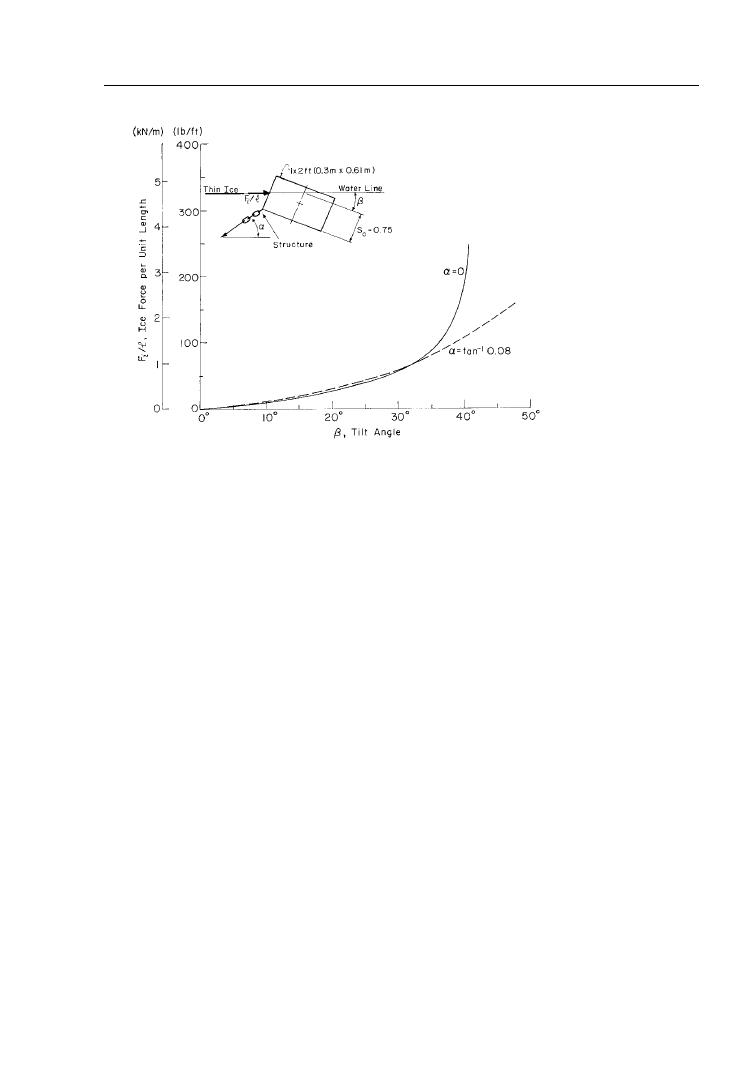
10. Ice restraint capac-
ity of a rectangular tim-
ber boom. Note that tan1
(0.08) = 4.6 so the boom
chain is nearly horizon-
tal. For the thin ice case,
the maximum ice re-
strain capacity of a rect-
angular timber boom is
on the order of 5080
lb/ft (0.731.2 kN/m).
and small rivers. Douglas fir has been the timber of choice be-
cause of its strength and durability, particularly under conditions
of constant wetting. Many of these booms were designed using 12-
14-in. (30- 36-cm) timbers, often in parallel, separated by tim-
ber blocks or steel struts, to increase the righting moment (Fig.
11b). In addition, some of these units have a second timber in-
stalled on the upstream face to increase the depth of the boom and
the capture efficiency (Fig. 5). The lengths of these timber boom
units are generally in the 20- to 30-ft (6- to 9-m) range, and the
spacing between boom units is optimum at about three to six ice
thicknesses. Timber booms have to be periodically removed from
the water to allow for complete drying.
Douglas fir timbers are still being used on Lake Erie, the Inter-
national Section of the St. Lawrence Seaway, and at Lake St.
Peter on the lower St. Lawrence River. However, the Canadian
Coast Guard and Hydro-Quebec are switching to steel pontoons
due to their lower maintenance costs and the decreasing availabil-
ity of large Douglas fir timbers. The steel boom units may be
rectangular as shown in Figure 11c, or may use steel pipe as the
flotation members as shown in Figure 11d and 11f. Some steel
pontoon booms are filled with foam to maintain floatation in the
event of damage and leaks. In this case, additional floatation is
needed to compensate for the added weight of the foam. Often, a
vertical face is installed on the upstream face of a pipe boom unit
(Fig. 11f), particularly in the case of shear booms. Recently, the
Canadian Coast Guard has had success with single-circular-


 Previous Page
