COLD REGIONS TECHNICAL DIGEST NO. 96-1
20
A
5'
(1.74 m)
3'
Stiffener
(0.9 m)
Cylindrical
Buoy
Steel
Band
4"
1/2" (13 mm) Bolt
(102 mm)
2"
A
A-A
(51 mm)
7/8" (23 mm) x 4' (1.22 m) Chain
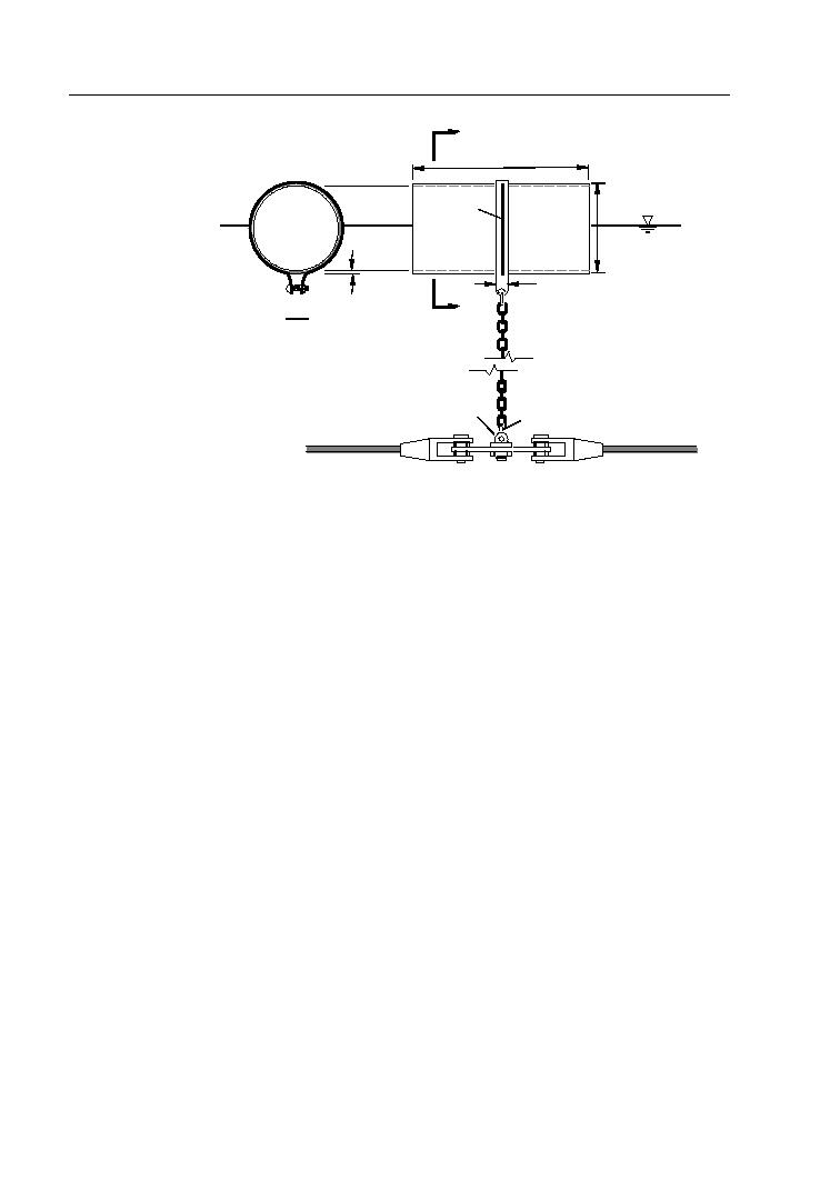
9. Example of junction
plate and float ar-
rangement. In this case
1 1/2" (38 mm)
a cylindrical float
1" (25.4 mm) Shackle
Eyebolt
supports the junction
2" (51 mm) Boom Cable
plate with a 4-ft (1.2-m)
2" (51 mm)
length of chain.
Wire Rope Socket
Boom unit design
Important considerations in the design of the actual boom units
are the type and thickness of the ice to be retained and the antici-
pated ice forces. The strength of the boom unit is also important,
since a boom unit must resist bending failure under the design
loads, particularly if large floes are expected to impact the struc-
ture. In addition, the boom unit must have sufficient frontal area
to capture floating ice and debris. Size is also an issue, because a
boom unit must be small enough to be easily handled by available
equipment during its annual installation and removal.
Ice restraint
The ice restraint capacity of a boom unit depends on the buoy-
capacity
ancy, the righting moment, the location of the anchor connection,
and the type of ice being retained. Figure 10, based on experimen-
tal data with thin ice covers, shows that a single 1 2 ft (0.3 0.6
m) timber boom, with a scope of 12.5 or more, has a maximum
load capacity in the 80 lb/ft (1.2 kN/m) range, above which the tilt
angle β reaches about 35, resulting in the ice overriding the
boom unit. With thicker, stronger ice covers, much higher loads
are possible, however. Some double pontoon booms have load
capacities as high as 500 lb/ft (7.3 kN/m). Measured force levels
listed in Table 1 give an idea of the maximum ice restraint capaci-
ties of various other types of booms.
Successful ice
Table 1 and Figure 11 illustrate a variety of successful boom
boom designs
unit designs. Many others are possible. For years, single timber
boom units (Fig. 11a) have been successfully used in both large


 Previous Page
