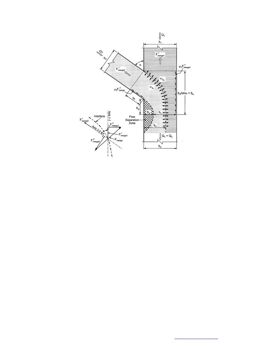
Figure 30. Lateral pressures associated with merging ice runs.
the axis of channel 1; 1 is the friction coefficient between ice and confluence
bank. The friction force is generated by the sideways force component F″merge1,
and it acts over the approximate length of bank shown in Figure 30. The
downstream extent of the friction force is difficult to determine precisely, it
likely does not extend further downstream than the section of greatest flow
contraction adjoining the flow separation zone.
2. When the flow from one confluent channel is considerably larger than flow
from the second confluent channel, which conveys ice, the dividing stream-
line can be pushed strongly to one side of the confluence. The change of
momentum of the larger flow Q1 exerts a hydrodynamic reaction force that
retards ice movement in the channel of lesser flow Q2. The ice is constrained
to a narrow band within the confluence entrance and backs up in influent
channel 2, as shown in Figure 31. For this situation, the reaction force com-
2F″flow2, retard ice movement from channel 2. Here, F″flow2 is the reaction
force component acting normal to the axis of channel 2, and 2 is the friction
coefficient between ice and bank. The friction force is generated along a short
distance of bank, as indicated in Figure 31.
3. Ice congestion adjacent to the confluence bar results in a jam in the conflu-
ence. This mechanism may arise when an ice run entering the confluence is
constricted by the presence of a bar, as illustrated in Figure 32, and jams at
the bar. The ice run may occur from one inflow channel or from both.
The three mechanisms give rise to relatively straightforward criteria for deter-
mining whether an ice jam will occur. The first two mechanisms require that the
37
Back to contents page


 Previous Page
