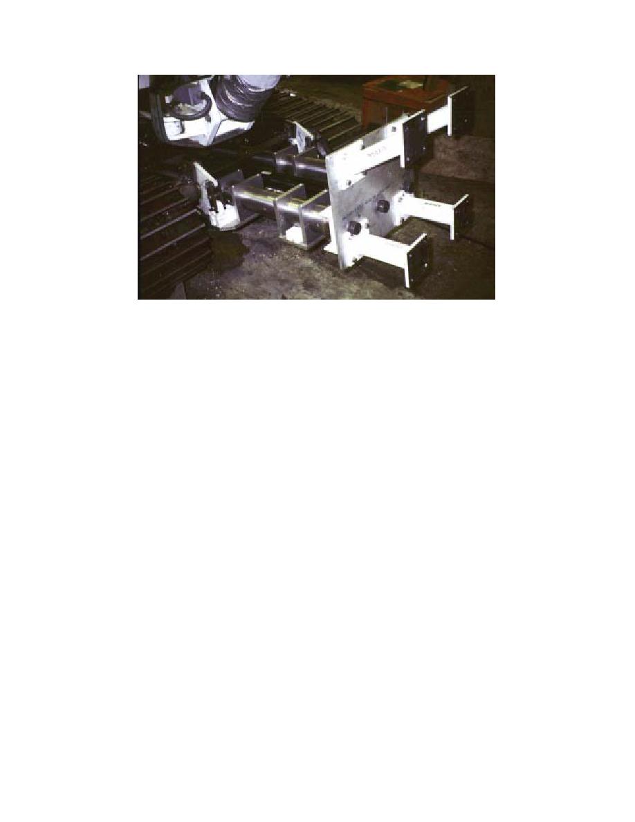
Figure 22. New snowblower frame.
promises the ability of the fan to process the ma-
with a V-groove band clamp system at this time.
terial. The solution was to add a 3-m sliding tube
This system is similar to the one used on the hori-
between the elbow and the blower to allow
zontal ducting. The redesign should prevent acci-
remixture of the material in the air stream. An
dental release of the tubes such as occurred sev-
additional benefit is increased ease of installation,
eral times during the tunneling operation. The
as this provides a radial degree of freedom in lo-
lifting bale for the vertical tubing was also replaced
cating the blower in relationship to the elbow.
with a simpler, easier-to-use system. Both changes
A new snowblower frame was installed (Fig.
will result in safer operations.
22), replacing the previous unit that did not ex-
The cutter drum was disassembled and rebuilt.
tend far enough and was not rugged enough. Two
The cutters were realigned to allow engagement
every 15, rather than every 45. A larger, special
bell cranks are used to lift the frame, putting the
lift cylinders in compression rather than tension
low-temperature chain was installed (no. 100 vs.
and thus reducing the chance of failure. The piv-
no. 80) as the previous chain had once again galled
ots are 3.8 cm diam., a substantial increase over
and no longer flexed freely. The 12.7-mm hydrau-
the previous 1.6-cm diam. pivot pins, and the as-
lic lines were replaced with 15.9-mm lines, cutting
sembly is lifted from two points rather than one,
line losses in half. The drum and snowblower
adding to the strength and stability of the unit.
pumps were replaced with more robust, higher
The horizontal duct assemblies were modified
capacity pumps, thus increasing the availability
to increase ease of use. The original extension
of speed and torque. Cavitation due to inad-
stops, which did not function as planned, were
equately sized suction lines prevented the comple-
removed and cable stays were added to prevent
tion of this task, however, although some simpli-
overextension of the tubes. Polyethylene was
fication of the hydraulics was carried out.
added to the tubes to decrease friction and galling
A few smaller modifications aimed at ease of
during relative movement between tubes. Col-
use were also made. The tilt indicators were repo-
lapsed-length stops were also added to prevent
sitioned to read "0" on the flat and level, and the
compression of the tube seals, and the trucks were
inclination directions changed to be more intui-
tied together with cables to reduce the stress on
tive ("+" is now up, "" down). The accumulator
the system when advancing after full extension.
valve for the tunneler was replaced, restoring func-
The force of extension will now be taken up pri-
tionality to the joystick controls. With these and
marily by the cables rather than the components
the other modifications noted in this section, op-
of the pup truck and duct assemblies.
eration and production of the tunneling system
The vertical ducting fasteners were replaced
should be much improved.
20


 Previous Page
