Table 1. Horizontal chip conveyance component
lengths (m).
Collapsed
Extended
Component
length
length
Pup truck
2.7
4.2
Duct truck
4.4
10.4
Flexible extension
1.1
--
Transition sled
2
--
joystick operation. This led once again to high oil
temperatures, sometimes reaching up to 80 C or
more, despite the 40 temperature of the tunnel.
With the tunneler slowly progressing through
the firn, a strategy was developed for the most
efficient deployment of the duct assemblies. As
Table 1 shows, the minimum length of the system
in its collapsed configuration is about 5 m. This is
with only the pup truck and transition sled de-
ployed behind the tunneler. After the tunneler
progresses to the maximum extension of the pup
truck, the 1.1-m section of flex hose is added. When
progress exceeds 4.4 m, the first section of duct
assembly is substituted for the pup truck and flex
hose. The pup truck is reinserted behind the tun-
neler as soon as possible, and the flex hose added
between the duct assembly and transition sled
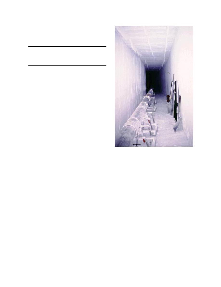
Figure 20. Extended ducts in tunnel.
thereafter. As progress continues, duct assemblies
are added when maximum extension is reached
with installed units (Fig. 20). The fully extended
removed, the bits swapped, the string relowered
length when all units are installed is over 38 m,
into the hole, and the last 0.3 m drilled. Two holes
giving a total extension of over 33 m (108 ft). Us-
were drilled side-by-side in one location, one for
ing this strategy, only half as many holes from the
the power cable, the other for the vertical ducting
surface to the tunnel need to be drilled for power
for the chip removal system. Survey markers on
and vertical tube access. Additional downtime is
the surface were used to determine the location of
required for the integration of each assembly, but
the holes.
this strategy still cuts the overall downtime almost
Before starting the tunneler each day, the heat-
in half.
ers had been run for at least 45 minutes. After the
By 25 November, progress was far enough (30
first surface deployment of the blower, however,
m) to redeploy the blower fan to the surface, drill
the machine was only warmed up 10 minutes, and
a set of access holes, and install the vertical tubing
within an hour the drum pump shaft failed. The
and transition sled. Because of the increased depth
probable cause of the failure of the pump shaft in
of the tunnel, 16 m vs. the original 10 m (max.),
January of 1996 could now be confirmed: inad-
special care had to be exercised while drilling the
equate warm-up time for the hydraulic system,
access holes. There are two bits available for the
resulting in high oil viscosity and high starting
drill, a single-cutter/single-helix bit (0.9-m long)
torque for the pumps. Overtorquing of the pump
and a double-cutter/double-helix bit (0.3-m long).
shafts led to overstressing of the cold, brittle shafts,
Because of the hardness of the snow and the length
initiating cracks that eventually led to torsion fail-
of the hole, the double-cutter bit was required.
ure. On this deployment we were prepared for a
However, the amount of drill string was insuffi-
shaft failure and had another set of pumps avail-
cient to reach the tunnel roof when the double-
able. The equipment was back in operation the
cutter bit was used, so the drill string had to be
next morning.
18


 Previous Page
