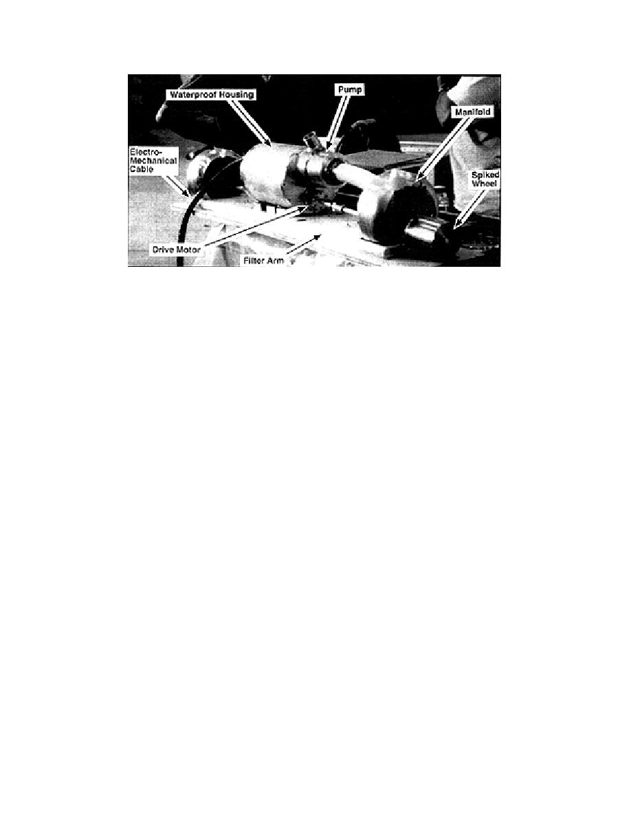
Figure 6. Major components of the 1.2-m operational collector.
minum shafts. The manufacturer rated these mo-
point. The same electromechanical cable operates
tors for a continuous duty torque of 4.6 Nm. At
either collector. Many of the individual compo-
each end of the arm, heavy aluminum assemblies
nents are interchangeable between the 1.2-m and
guide the motor shafts and help the collector con-
2.4-m collectors, providing a level of redundancy;
form to surface curvature. In addition, one of these
we also purchased numerous spare parts, includ-
end assemblies contains an internal flow passage
ing a second electromechanical cable.
(manifold) to connect the pump to the two ple-
The underwater video camera consisted of a
num chambers along the arm.
high-resolution color camera and a zoom lens
An electromechanical cable connects to the cen-
mounted inside an aluminum pressure housing
tral housing via a waterproof connector. This cus-
(rated to 1000-m water depth). A thermostatically
tom-made, LDPE-jacketed cable contains 19 elec-
controlled heater ensured normal camera opera-
tion at 50C. Two independently operated 500-
trical conductors to operate the collector, under-
water video camera, and lights at the SPWW. It
W waterproof lamps provided illumination, with
also contains an internal Kevlar braided jacket,
one projecting sideways from the collector and one
with a rated breaking strength of 4500 N, to act as
projecting downward from the camera. Water-
a strength member. Mechanical attachments at the
proof connectors connected the camera and lamps
housing and end assembly transfer the weight of
to the electromechanical cable. This equipment
the collector to the cable. This 17-mm-diam. cable
was operated through a video control unit and a
is quite flexible and can bend to a minimum ra-
video monitor at the surface.
dius of 30 cm at 50C. All collector and cable com-
The video system provides the visual feedback
ponents were accepted for use in the SPWW. Fig-
needed to maneuver the collector. We control the
ure 7 shows a schematic of the 1.2-m collector,
rotation speed and direction of drive motors us-
cable, camera, and lights in the SPWW.
ing two DC power supplies at the surface. Cur-
We also constructed a 2.4-m-long, central-slot
rent limiters ensure operation of the motors be-
collector (Fig. 8). We chose this length for the filter
low their continuous-duty torque ratings. A simple
arm because the longest sheet of LDPE available
rectifier and switch are sufficient to operate the
to us was 2.4 m. This collector utilizes similar com-
collector pumps. We can monitor the current
ponents but is completely independent of the 1.2-
drawn by the pumps to determine the approxi-
m collector. It possesses two waterproof housings,
mate flow rate.
each fitted with a pump and drive motor. Both alu-
A reversible, constant-speed winch raises and
minum end assemblies contain internal manifolds
lowers the collector via the electromechanical
to connect the pumps to the plenum chambers in
cable. A set of slip rings provide electrical connec-
the arm. We can replace one drive wheel and mo-
tions between the rotating cable and the station-
tor with a 90 gear box and rotation transducer to
ary surface equipment. The cable passes over a 76-
measure the rotation of the arm around a pivot
cm-diam. sheave mounted on top of a 3.6-m high
9


 Previous Page
