the size range 501000 m without bias to compo-
the area swept. Separate filter chambers distrib-
uted along the arm would reveal information
sition (e.g., toward magnetic particles). Its collec-
about the radial distribution of particles. Alterna-
tion efficiency should be high (and we should
tively, we could independently operate a drive
measure it). It should cause no physical or chemi-
motor at either end of a shorter version of the col-
cal changes to the particles. Its design should mini-
lector to maneuver it over undulating well-bot-
mize handling losses after collection. It should give
tom topography. An underwater video camera
reliable performance and be adaptable to un-
would help maneuver the collector and document
known bottom surface conditions. In addition, its
the area swept.
design should minimize the possibility of it be-
This concept contains many advantages over
coming stuck in the well.
alternatives considered. Suctioning particles by en-
training them in a water stream should avoid any
Preliminary design
compositional bias in the collection (assuming that
We had a brainstorming session to gather pre-
the water flow is high enough to entrain the heavi-
liminary collector concepts. After reviewing these
est particles of interest). Down-hole filtering
ideas, we selected a concept that involved down-
avoids the need to pump water and particles to
hole suctioning and filtering of the particles by a
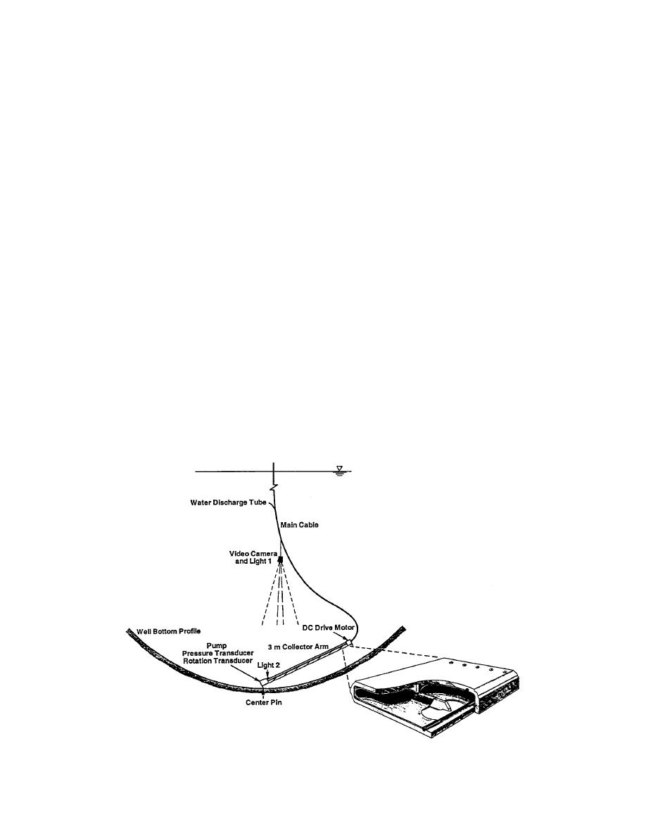
mobile collector controlled from the surface. Fig-
the surface, saving pumping requirements and
avoiding particle damage and losses within the
ure 3 shows this concept as originally envisioned.
piping system. Indeed, our design minimizes par-
It utilizes the unconstrained, vertical dimension
ticle damage and losses by incorporating the fil-
of the well neck to maximize the filter capacity and
ter immediately downstream of the intake slot.
the area swept out by the collector in a single pass.
A pump develops a high-speed flow to suction
Further development of this concept required
basic data on the number of particles expected (to
particles through a slot along the underside of a
determine filter capacity), the flow velocity needed
long, flexible arm containing a filter. The filter arm
to entrain the particles of interest, and the pump-
would be formed from a flexible, drinking-water-
ing losses expected (to size the pump). We also
safe plastic to allow it to conform to the curved
investigated several fabrication options to incor-
well bottom. We could drive the long arm around
porate a filter into the collector arm.
in a circle and measure its rotation to determine
Figure 3. Original collector concept (layout and filter arm cross-section).
5


 Previous Page
