January 1995. The reservoir has reached a rela-
COLLECTOR DESIGN
tively stable size of about 24 m diameter and 16 m
depth and contains about 5,000 m3 of water (based
Technical objectives
Our technical objectives were (a) to collect es-
on water consumption and depth data, Appendix
sentially all of the micrometeorites from a large,
A). The present consumption rate is about 2,000
m3 (about 2 million liters) per year. The pump
known area of the well bottom, and (b) to be ca-
pable of returning to the same area of the well
draws water from about 1 m below the water sur-
bottom annually. Assuming that the micromete-
face. About 10% of the water is consumed and the
orites form a lag deposit, meeting these technical
rest is heated, using waste heat from the station,
objectives would allow us to calculate flux rates
and returned to the well.
and document any temporal changes in the com-
The flow rate of returning water is about 1
L s1, and it is discharged 3 m below the water
position of the particles (i.e., meet the scientific
objectives).
surface through a nozzle designed to produce a
uniform, 90 cone-shaped jet. Peak discharge ve-
locity 1 m away from the nozzle should be less
Design requirements and performance criteria
than 1 mm s1, and no remnants of the jet
The nature of the SPWW imposes strict require-
ments on the collector design. The collector must
should persist at the well bottom. Rather, the
not degrade water quality under any circum-
jet and heat input probably establish large-scale
stances. It must fit down a 30-cm-diam. well neck
circulation cells in the pool. It seems very unlikely
and survive a cold soak at 50C during its de-
that circulation velocities at the well bottom would
scent to the well pool. It must operate remotely in
be adequate to entrain the micrometeorites of
about 20 m of water at a distance of 200 m below
interest.
the snow surface.
The effort required to model the flow distribu-
In addition, we specified several performance
tion in the SPWW was beyond the scope of our
criteria to help guide our design selections. The
work. However, we estimated the velocities
collector should collect essentially all particles in
needed to transport micrometeorites and assessed
whether such velocities were likely to be present.
To initiate movement of a 50-m particle with a
density of 2.5 g cm3 (stony or glassy micromete-
Winch Room
orites), flow velocity along the well bottom would
Surface
Lab
Wellhouse
need to exceed about 6 cm s1 (ASCE 1975). The
micrometeorites of interest are generally larger or
2.5 m
EPDM
Protective
more dense and hence would have higher thresh-
Mat
olds. It seems unlikely that bottom velocities
would exceed threshold values, given that veloci-
ties 1 m from the nozzle are substantially lower.
60 m
1500 A.D.
We therefore thought that micrometeorites would
form a lag deposit on the well bottom as they are
melted out of the ice.
70 m
Originally we had planned to deploy the col-
lector during an annual maintenance period when
the well's pump and hoses were removed for ser-
80 m
vicing.* However, space in the well house is very
limited, complicating collector deployment, and
our collection time would have been restricted to
90 m
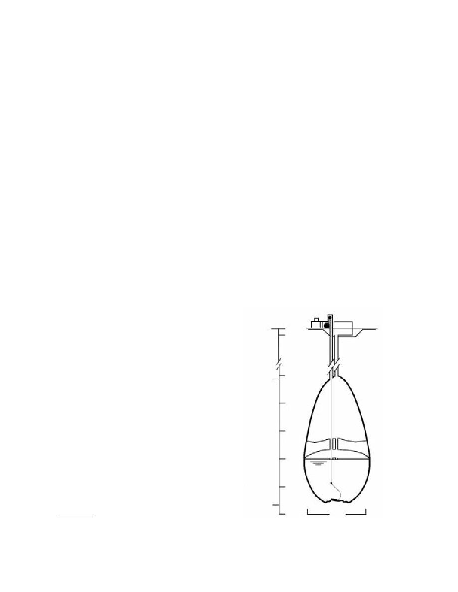
a few hours. For these reasons we drilled a sec-
Water Level
ond access hole, about 2 m from the central
Camera
hole, and had a separate work area constructed
and Lamp
100 m
(Fig. 2).
Collector
1000 A.D.
110 m
24 m
Figure 2. Approximate size and shape of the South Pole
*J.H. Rand, 1996, Ice Engineering Division, CRREL, per-
Water Well in December 1995.
sonal communication.
4


 Previous Page
