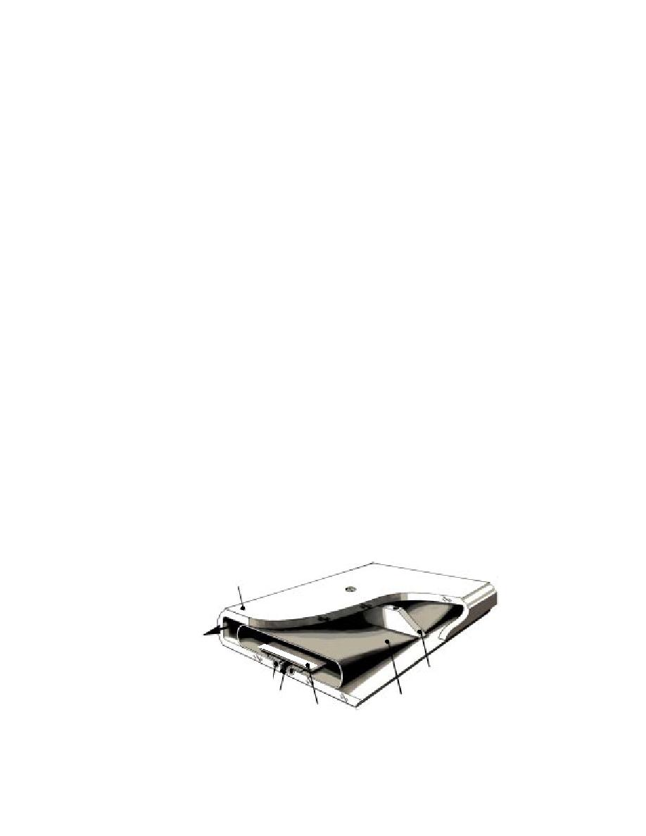
formed by folding and securing the two sides of
These tests also revealed several disadvantages
the arm.
of our original, front-slot design: (a) filter installa-
An important modification resulted from these
tion was awkward, (b) it would be difficult to con-
trol the slot width if the arm was made from flex-
tests. We found that particles could escape back
ible plastic, and (c) the flow-collecting plenum
through the intake slot when we pulled the col-
channel downstream of the filter needed to be
lector out of the water and the pump lost suction.
larger to reduce the pressure drop (and hence
To prevent this "backflushing" of particles, we
installed a thin strip of 1-m filter fabric (later
maintain a more uniform intake velocity distribu-
tion) along the collector arm.
replaced with a strip of thin LDPE) to serve as a
For these reasons, we modified the collector-
flow check valve. This solved the backflushing
arm design to produce a central intake slot and a
problem.
flow plenum channel along each side (Fig. 5). The
arm can be fabricated from a machined and folded
piece of low-density polyethylene (LDPE). O-rings
FINAL DESIGN
secure the sides of the filter fabric adjacent to the
intake slot, and folding results in a filter pouch.
We constructed two fully operational collectors
End caps with O-rings seal the filter pouch and
based on the central-slot design. We initially built
prevent flow leakage. Aluminum ribs spaced
a 1.2-m-long prototype to assess the design's
along the arm maintain the geometry of the arm
maneuverability and collection efficiency on iced
and slot and prevent collapse of the plastic under
surfaces. This prototype also provided us with a
suction. Although this design draws flow equally
shorter, more maneuverable collector to use in the
from both directions under the collector, resulting
SPWW as an alternative to the 3-m-long device
in lower velocities along the ice surface, we felt
originally planned.
the manufacturing, assembly, and flow-distribu-
Figure 6 shows the basic features of the 1.2-m
tion advantages outweighed this disadvantage.
collector. The filter arm consists of a single ma-
We conducted flow tests on a 30-cm-long 18-
chined and folded sheet of LDPE with the same
cm-wide model of the central-slot collector arm.
internal layout as the 30-cm-long model (Fig. 5).
This model developed better flow distribution, as
This arm is quite flexible, allowing the collector to
evidenced by a lower pressure drop through the
conform to a surface curvature of about 2 m ra-
filter and negligible pressure drop along the ple-
dius (30 cm rise over 1.2 m). The LDPE also exhib-
num channels. It also easily suctioned up the test
its low friction on wet ice. A central, waterproof
particles. No appreciable plugging of the filter oc-
aluminum housing contains the pump and drive
curred even though it collected almost 200 g of
motors and all electrical connections; the externally
mounted pump housing is also aluminum. O-rings
material, and the resulting minimum flow rate was
0.33 L s1. It was also much easier to install and
seal the removable end plates and motor shafts.
remove filters with this model. With careful ma-
Traction is via heavy, stainless steel, spiked wheels
chining, a relatively uniform intake slot was
driven by DC gear motors through articulated alu-
Folded LDPE
Flow Channel
to Pump
Aluminum Rib
ORing
2 mm Intake Slot
Filter Fabric
(53 m mesh)
Thin LDPE Strip
(check valve to prevent
backflushing)
Figure 5. Final collector-arm cross-section.
8


 Previous Page
