APPENDIX A: DESIGN OF RIPRAP PROTECTION AGAINST WAVES
Wind-generated waves induce one of the most
ture, and clearly defined damage level, are given
powerful forces on coastal structures. A given struc-
in CIRIA Special Publication 83 (1991).
ture may be subjected to nonbreaking, breaking,
and broken waves during different stages of a tidal
Design of riprap protection of
cycle. The significant wave height is obtained from
flood control channels
The guidance for the riprap slope protection of
historical data to represent the wave condition at a
flood control channels (U.S. Army Corps of Engi-
site. The riprap stability formula (Coastal Engineer-
neers 1991) applies to open channels having a slope
ing Research Center 1984), based on small-scale
of less than 2%. The ability of the riprap material
and large-scale model testing, is given by:
to resist the erosive forces of channel flow depends
ρr gH 3
on the following parameters: shape, size, weight
W50 =
(A1)
KD (Sr - 1)3 cot θ
and durability of stone; gradation and layer thick-
ness of riprap; and alignment, cross section, gradi-
where W50 = median weight of individual armor
ent and velocity distribution in a channel. The ba-
unit in primary cover layer,
sic equation for the representative stone size in
ρr = density of armor unit
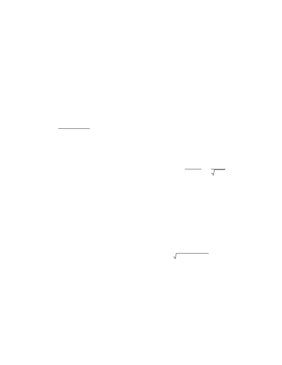
straight or curved channels is given by
γ
v
2.5
1/ 2
H = design wave height at the structure
= SfCsCvCT d
w
D30
(A2)
(≈ H1/10 average of the highest 10%
γ s - γ w
K1gd
of all waves)
Sr = ρr/ρw ratio of the armor density to
where D30 = riprap size of which 30% is finer by
the water density
weight
θ = angle of structure slope measured
Sf = safety factor (≈ 1.1)
from the horizontal
Cs = stability coefficient for incipient
KD = stability coefficient that varies pri-
failure
marily with the shape of the armor
Cv = coefficient related to vertical
units, roughness of the armor unit
velocity distribution
surface, sharpness of edges, and the
CT = thickness coefficient
degree of interlocking obtained in
d = local depth of flow
placement
γw = specific weight of water
= 3.5 for breaking waves
γs = specific weight of stone
= 4.0 for nonbreaking waves.
v = local average velocity
K1 = side slope correction factor =
Because of its simplicity, the above formula is
1 - (sin2 θ / sin2 φ)
easy to work with. The values of KD have been de-
θ = angle of side slope
rived for a wide range of armor units and configu-
φ = angle of repose
rations. However, the above formula has many
limitations. This formula is based on small-scale
model tests, and does not account for the level of
Recommended values of various coefficients
damage, storm duration and wave period.
and factors are given in EM 1110-2-1601 (U.S. Army
As reported in CIRIA Special Publication 83
Corps of Engineers 1991). Special attention needs
(1991), Van der Meer (1988) proposed a number of
to be given for the design of toe protection and fil-
formulas for deep and shallow water conditions
ter material between the riprap and the underly-
and for plunging and surging waves. These for-
ing material. Construction quality needs to be
mulas, which incorporate the effect of wave period,
maintained for the size, the shape and the grada-
the storm duration, the permeability of the struc-
tion of stones.
23


 Previous Page
