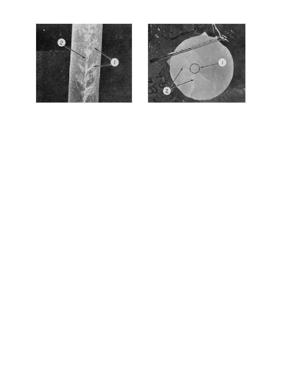
a. Vertical sea ice core showing relative configuration of
b. Horizontal section across a brine drainage tube. Radi-
brine drainage feeder channels (1) extending outward at
ating out from the central brine drainage tube area (1) are
≈ 45 from the brine drainage tube (2).
numerous brine drainage feeder channels (2).
Figure 2. Sea-ice core sections (from Morey et al. 1984).
process the seawater at the ice growth interface is
colder, brine flow decreases and much of the drain-
replaced by supersaturated brine that slows the
age system is transformed into a series of brine
rate of solidification. As with the frazil/granular
and gas cells separated by necks of ice (Doronin
surface ice layer, some brine and gas become
and Kheisin 1975). The salinity at any given depth
trapped between the platelets, as depicted in Fig-
now decreases slowly during the remainder of
ure 1. As the ice sheet continues to grow and
the growth season. Drainage systems form again
becomes colder, the film of brine between the ice
during the melt season (Nakawo and Sinha 1981).
platelets reduces in volume due to expulsion and
Near-freezing temperatures and solar radiation
drainage processes as well as the freezing out of
heating cause melting, "corrosion pockets" form
fresh water from the brine to the surrounding ice
in the ice surface, and internal melting occurs at
surface. The now-isolated brine inclusions are
crystal boundaries, old brine drainage routes,
called brine pockets. They are frequently described
flaws, etc. (Bennington 1967, Cox and Schultz
as ellipsoids, but in fact can have rather complex
1980). The corrosion pockets contain liquid with a
geometries, depending on ice growth rate and
high salt concentration originating, for example,
temperature.
from the salt residue of the >50‰ salinity brine
Brine expulsion and drainage occur along a
that was ejected to the surface during initial ice
flow route that resembles the trunk and branches
sheet formation (Burke 1940, Zubov 1945, Martin
of a tree, called a drainage tube and channels,
1979, Drinkwater and Crocker 1988, Perovich and
respectively. A vertical drainage tube and chan-
Richter-Menge 1994), from the typically high-sa-
nel system in Beaufort Sea congelation ice is
linity frazil or granular ice surface layer (Martin
shown in Figure 2. From 1.5-m-square ice blocks
1979) or from brine concentrated in an ice surface
removed from 1- and 1.8-m-thick ice sheets in the
layer formed as a result of ice sheet flooding. The
Beaufort Sea, I found the drainage tubes at the
enriched brine then melts into the ice sheet, re-
bottom of the ice to be spaced 5 to 17 cm apart,
opening or enlarging the old drainage systems as
but they average 10 cm apart. These spacings are
the brine wave descends to the sea. The cold,
in agreement with the findings of Martin (1979),
high-salinity (60 to 70‰) drainage (Lewis and
Wakatsuchi (1983), and other investigators.
Milne 1977) is followed by increasingly fresher
Wakatsuchi also reported that the spatial density
flow resulting from the pure-ice melt or is re-
of brine tubes depends on the growth rate. The
placed by an upward flow of less dense seawater
faster the growth rate, the more drainage tubes
(Edie and Martin 1975). Depending on the brine
per unit area. The brine channel inclination varies
temperature and volume flux and seawater cur-
from 40 to 54, but averages 45 (Lake and Lewis
rent velocity, on exiting the ice the brine drainage
1970, Criminale and LeLong 1984).
can freeze the seawater around the periphery of
Brine drainage is high during initial ice for-
the descending brine plume, forming long, deli-
mation, but as the ice sheet thickens and becomes
cate, thin-walled hollow ice stalactites (Fig. 3) that
2


 Previous Page
