1.0
0.8
Dry
Surface
0.6
80% RH
θ
90
99
0.4
0.2
0
0.2
0.4
0.6
0.8
1.0
R
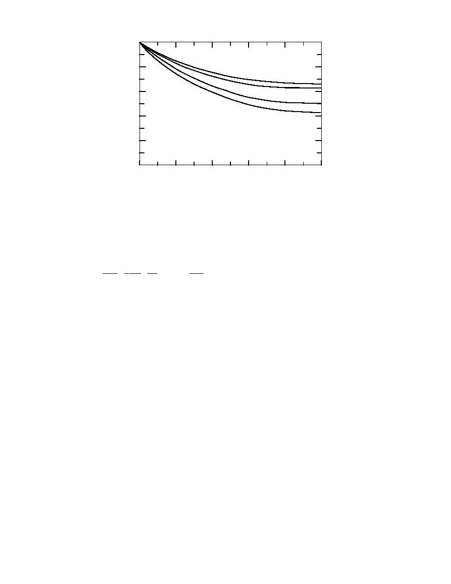
Figure 11. Temperature distributions in a radial fin with moisture
condensation from surrounding air. Adapted from Elmahdy and
Biggs (1983).
where the constant a (given by eq 54) and c are to be determined from the psychrometric
data for the range of temperatures considered. Substituting for ωT,s from eq 60 into eq 58,
the differential equation for Tf becomes
d2Tf 1 dTf 2h
(Ta - Tf ) - kw (ω a - c - a Tf ) hfg = 0 .
2hm
+
-
(61)
dr 2
r dr kw
A sample of numerical solution of eq 61 subject to boundary conditions eq 59 is shown
in Figure 11. In this figure, the dimensionless temperature θ = (Ta - Tf )/(Ta - Tfb ) is plotted
against dimensionless radius R = (r rb)/(rt rb) for dry as well as wet operating
conditions. The results are based on the following data: Ta = 16C, Tfb = 7C, h = 57 W/m2
C, and N = (rt - rb )(2h / kw)1/2 = 0.82. It can be seen that the temperature profiles for a wet
fin lie below those of a dry fin. As the relative humidity of air increases, the driving
potential for mass transfer increases, which leads to a higher latent heat transfer and
higher fin temperature. Note that lower values of θ mean higher fin temperatures
Considering a typical fin surface element 2πrdr, the heat transfer dq to the element can
be expressed as
[
]
dq = h (Ta - Tf ) + hm (ω a - ω T,s ) hfg (2πr dr) .
(62)
Allowing for heat transfer to both faces of the fin and integrating eq 62, the total heat
transfer to the fin is found to be
[
]
rt
q=∫
4π h(Ta - Tf ) + hm (ω a - ω T,s ) hfg r dr .
(63)
rb
The maximum or ideal heat transfer to the fin occurs if the entire fin surface is main-
tained at temperature Tfb, and is therefore given by
)[
)] .
(
(
qideal = 2π rt2 - rb h(Ta - Tfb ) + hm ω a - ω b,s
2
(64)
19


 Previous Page
