1
2
3
4
a. Southeast corner.
a. Front view.
1
2
3
4
b. Northwest corner.
b. Rear view.
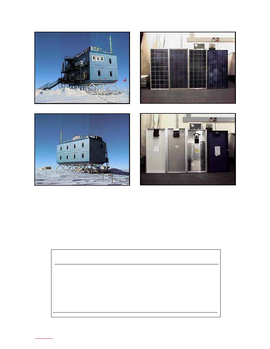
Figure 1. Atmospheric Research Laboratory (25 Novem-
Figure 2. PV panels that were evaluated (1--KYOCERA;
ber 1997).
2--PhotoComm; 3--ASE Americas; 4--Solarex).
Mechanical and electrical specifications
KYOCERA model LA-51
for each PV panel
These cells are encapsulated between a tempered
The PV panels (Fig. 2) selected for the test were pur-
glass cover and an EVA pottant, with PVF and alumi-
chased from four manufacturers--KYOCERA, Photo
num foil back sheets to provide maximum protection
Comm, Inc., ASE Americas, and Solarex. The following
from the most severe environmental conditions. The
PV panel mechanical and electrical specifications came
entire laminate is installed in an anodized aluminum
directly from the manufacturers' data sheets (Table 1).
Table 1. Specifications of PV panels tested.
KYOCERA
PhotoComm
ASE Americas
Solarex
Surface area (in.2, m2)
679
0.438
674.1
0.436
676.4
0.436
676.4
0.436
Length (in., mm)
38.8
985
38.3
973
38.0
965
36.9
937
Width (in., mm)
17.5
445
17.6
448
17.8
452
19.74
502
Thickness (in., mm)
1.4
36
1.75
44
2.0
51
2.0
51
Weight (lb, kg)
13
5.9
12
5.4
13.5
6.12
13.9
6.31
Rated power (W)
51
47.2
50
50
Voltage (nominal) (V)
16.9
17.1
17
12
Current (test) (A)
3.02
2.8
2.9
3.12
Voltage (Voc) (V)
21.2
21.2
20.7
21.1
Current (Isc) (A)
3.25
2.9
3.2
3.17
2
to contents


 Previous Page
