APPENDIX B: METHODS USED TO RECALCULATE DESIGN CURVES FROM
BARENBERG ET AL. AND GIROUD AND NOIRAY.
The design method presented by Barenberg et al. (1975) necessitated the solving
of equations for the aggregate thickness required, given a known range of soil co-
hesion. For Giroud and Noiray (1981), equations for cohesion were solved for a
given range of aggregate thickness. Mathcad 6.0 (Mathsoft 1995) was used to solve
these equations and generate design curves as well as to produce a symbolic equa-
tion for the aggregate thickness required for the Barenberg et al. (1975) approach.
SOLUTION FOR DEPTH OF AGGREGATE FOR
BARENBERG DESIGN METHOD
Barenberg et al. (1975) assumed that the stress transmitted to the subgrade sur-
face through the aggregate layer can be approximated by a Boussinesq stress distri-
bution through an elastic, homogeneous, isotropic half-space. The ratio of vertical
stress at depth, z, to the stress on a uniformly loaded circular area in an elastic,
homogeneous, isotropic solid bounded by a plane horizontal surface is (Newmark
1942)
σ = 1 cos3 α
(B.1)
where α = a tan(r / z), and r is the radius of the circle and z is the depth at which
the stress determination is desired (z is located directly below the center of the
circularly loaded area).
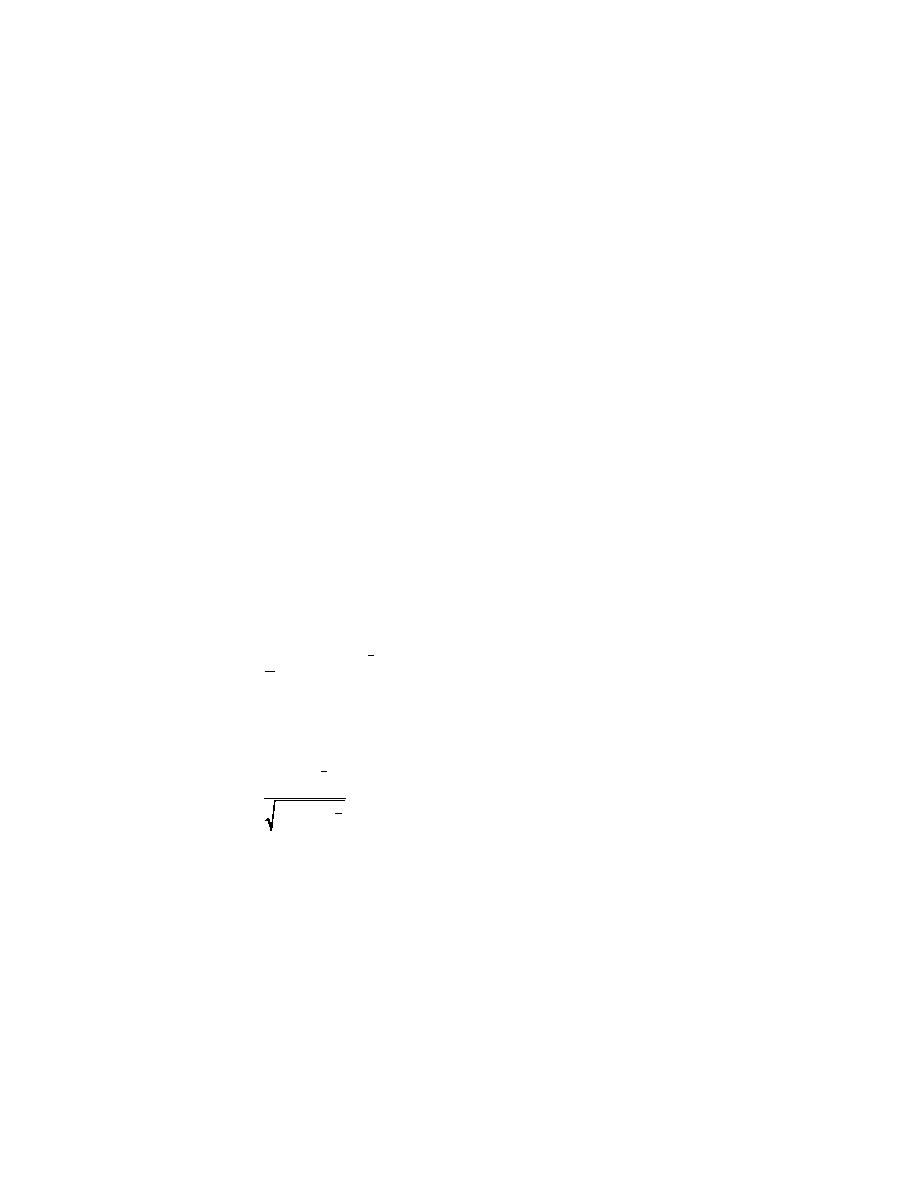
The expression for α is substituted into eq B.1 and is rearranged to yield
1
r
a tan = a cos(1 σ) .
3
(B.2)
z
This equation is then solved for z (using Mathcad 6.0) to yield
1
(1 σ)
3
z = r
.
2
1 (1 σ) 3
For a range of soil cohesion, c, and a known applied stress, the stress that can be
tolerated at the subgrade is given by either 3.3 c (without geotextile) or 6.0 c with
geotextile. Thus, the ratio of soil strength to applied pressure, e.g., σ = (3.3c/contact
pressure) is used to determine the thickness of the aggregate layer needed. Ex-
ample work sheets from the Mathcad 6.0 software used to make these calculations
follow.
25


 Previous Page
