Table 13. Explanation of the subsurface routing variables.
Initial
Variable
Description
condition
Units
km2
DA
drainage area
63
FATR
percentage of zone 2 simulated by GROFF2
0.95
decimal
m3/s
I
percolation conversion factor
0.13
m3/s
INFLOW_II
inflow to groundwater or subsurface storage
0.13
m3
INIT_ISBS_ISTOR
initial groundwater or subsurface storage
8.03
m3/s
INIT_IOUTFLOW
initial outflow from subsurface storage in zone 2
1.61
KSSa
adjusted subsurface flow recession constant
5
h
m3/s
OUTFLOW_III
outflow from ground water or subsurface storage
1.61
PCT 2
areal fraction of zone 2 in the watershed
0.22
decimal
m3/s
QSS
initial subsurface flow
0.046
SBS_STOR
groundwater or subsurface storage
8.03
mm
SBS STOR
INFLOW II
OUTFLOW II
KSSa
I
DA
PCT 2
FATR
INIT SBS STOR
QSS
INIT OUTFLOW
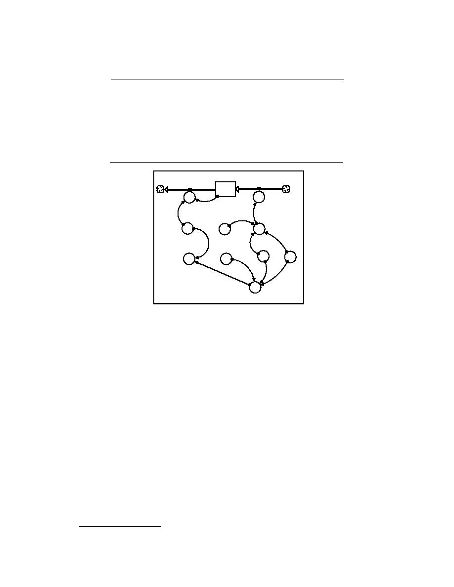
Figure 20. Subsurface flow routing. This structure is located beneath
GROFF2 and routes percolation from the bottom soil layer through a linear
reservoir to simulate the average time for a molecule of water to travel
through zone 2 of the watershed as subsurface flow. SBS_STOR,
INFLOW_II, and OUTFLOW_II form the linear reservoir. INFLOW_II, the
input to the linear reservoir, contains the value of "I." "I" converts the per-
colation (P) generated from GROFF2 from mm/h to m3/s. DA, PCT_2,
FATR, and P (from GROFF2) are used to calculate "I." For simplification,
"P" is not shown here. The output from the linear reservoir in
OUTFLOW_II is delayed to simulate the average amount of time for a mol-
ecule of water to travel through zone 2 of the watershed as subsurface flow.
The delay of flow in OUTFLOW_II is calculated by KSSa and SBS_STOR
(eq 43). INIT_OUTFLOW and KSSa are used to calculate INIT_SBS_STOR
(eq 44). QSS, PCT_2, and FATR are used to calculate INIT_OUTFLOW (eq
45). Only the main objects of SBS_STOR_&_FLOW_1 are shown here.
OUTFLOW_II (eq 40). INFLOW_II contains the value of I (eq 41). "I" is calculated with DA,
FATR, P from GROFF2, and PCT_2 (eq 42). "P" is not shown for simplification. OUTFLOW_II is
calculated with SBS_STOR and KSSa (eq 43). INIT_SBS_STOR is calculated with
INIT_OUTFLOW and KSSa (eq 44). INIT_OUTFLOW is calculated with QSS, PCT_2, DA, and
FATR (eq 45).
Equations 38 and 39 are the basic linear reservoir routing equations found in the literature from
which the linear reservoir routing equations in Object-GAWSER are derived (Veissmann et al.
1977).*
* Equations 38 and 39 are equivalent to equations 13.1 and 13.33 in Veissmann et al. (1977).
31


 Previous Page
