neers 1985), were carried away in the late seven-
operation and maintenance of the pontoons
ties by a large floe that rotated up from the
were costly and difficult. Once formed, the ice
southwest quadrant of the lake. After this inci-
cover behind the structure prevents floes and
dent the booms were not installed again.
brash from contributing to potential jams in the
Upstream of Lake St. Peter, 2300- and 3300-ft-
navigation channel downstream of the city. In
long booms stabilize the ice cover along the riv-
addition, the cover behind the ICS traps and
er's left side at Lanoraie and Lavaltrie. Most of
stores much of the frazil generated in the
the booms are of conventional design, with 14-
Lachine rapids upstream of Montreal. Before
in. 22-in. 30-ft timbers connected to a series
construction of the Montreal Harbor ICS, the ice
of cables with 400-ft-long spans. However, sev-
cover on Laprairie Basin formed only after the
eral test spans made up of 30-in.-diameter cylin-
natural ice cover had progressed from Lake St.
drical steel pontoons are showing promise in
Peter up to Montreal (Donnelly 1966). Should
terms of increased capture efficiency and re-
the cover progress as high as Montreal, the ICS
duced cost.*
was intended to capture arriving ice from
The overall goal of the islands and booms is
upstream to reduce the ice jam flood threat to
to allow as little ice as possible to enter the navi-
the city. Due to successful ice breaking and
gation channel. The structural measures make
flushing efforts by the Canadian Coast Guard,
up only part of the overall ice management
the ice cover has not reached the city since win-
scheme, however. Continual ice breaking and
ter-long navigation began in the mid-sixties, so
flushing efforts, combined with routine airborne
the structure has never been tested in this worst-
surveillance, are also critical.
case scenario. At a cost of million Canadian
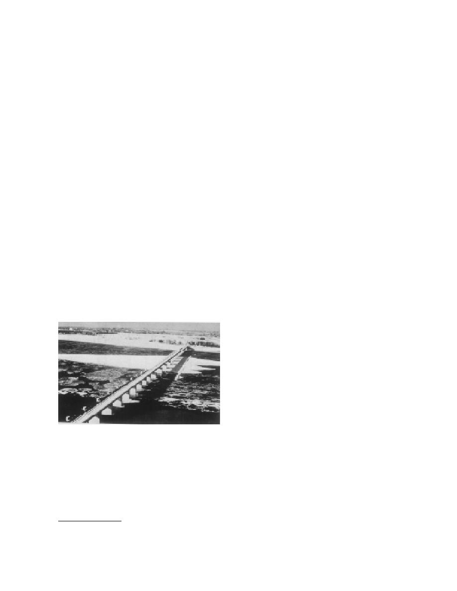
The Montreal Harbor ice control structure
in 1965, the Montreal Harbor ICS is possibly the
(ICS), located at the upstream limit of winter
most expensive ice control structure ever built
navigation on the St. Lawrence, consists of a row
(Donnelly 1966, Lawrie 1972).
of concrete piers, spaced at 88-ft centers, over a
On the Trollhatte Canal in Sweden, ice
total width of 1.3 miles. Figure 2 is an aerial
booms, rock-filled cribs and dolphins are used
view of the structure. Originally steel pontoons
to stabilize sheet ice along the sides of the navi-
(5.5 5.8 ft in cross section) floated in guide slots
gation channel. As with the lower St. Lawrence,
winter-long navigation is the goal, from Swe-
den's west coast to ports on Lake Vanern. Ice
breaking and flushing, bubblers and lock wall
heaters along with airborne surveillance comple-
ment the structural ice control methods (Solve
1986).
Ice control at lakeriver confluences and
channel constrictions
Lake-to-river confluences present a special ice
control problem. Although there is a tendency
for ice arches to form naturally at these loca-
tions, wind and wave effects, as well as vessel
passages, can disrupt arch formation, causing
lake ice to enter and sometimes jam in the nar-
Figure 2. Montreal Harbor ice control structure.
rower channel downstream.
(From Lawrie 1972.)
The Lake Erie ice boom, located near Buffalo,
between the piers with the goal of initiating an
New York (Fig. 3), prevents, to a large degree,
ice cover as early as possible. It was later found
lake ice from entering the Upper Niagara River.
that the pontoons were unnecessary, since the
The 8800-ft-long boom has 22 spans, each 400 ft
piers alone promoted the formation of a stable
long; each span is made up of 13 timbers, each
16 in. 22 in. 30 ft. Occasionally, during the
ice cover in Laprairie Basin, upstream of the
structure. This discovery was fortunate, since
early winter, wind-driven lake ice in the 4- to 8-
in. thickness range will override the boom, how-
ever. These lake ice runs may result in massive
* Personal communication with Brian Morse, Canadian
jams in the Upper Niagara River, causing flood-
Coast Guard, April 1994.
4


 Previous Page
