Heeling system
In earlier times, the crews of cargo
ships that were stuck in ice found that lift-
ing a heavy weight by a crane and swing-
ing it sideways helped to free the ship.
This experience led the designers of ice-
breakers to install heeling tanks on each
side of a ship and to provide for pump-
ing large amounts of water back and forth
between the tanks. The continuous roll-
ing motion of a ship facilitates its prog-
ress in ice with less power.
Now most operators consider the heel-
ing system important for improved
icebreaking and maneuvering. Almost all
Baltic icebreakers have heeling tanks. The
Swedish icebreaker Oden was fitted with
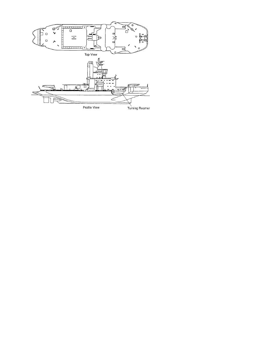
Figure 19. Outboard profile and topside deck plan of the Swedish a fast heeling system that allows full heel-
icebreaker Oden.
ing in 15 seconds (Backman 1994). This
has enabled Oden to make continuous
progress in heavy ridges. Oden is also fitted with
case of Inerta 160, the wear-off starts at the cracks
turning reamers located above the ice surface on
caused by the deformation of the shell plating at
each side just aft of the bow (Fig. 19), and when
the edges of the ship's frames. The wear-off is
the ship is heeled over, one reamer comes in con-
intensified in heavily loaded areas, such as the ice
tact with ice to help the ship to turn sharply into
belt in the ship's forebody, and during operations
the heel (Johansson et al. 1994). Thus, a heeling
in heavy ice and especially in the presence of soil
system in combination with the turning reamers
or sand mixed in ice. To correct this deficiency in
has improved the maneuverability of Oden by de-
Inerta 160, stainless-steel-coated surfaces, though
creasing the turning radius. With improved
expensive, were developed because of their high
maneuverability, polar ships are often able to make
wear resistance and low-friction properties. Ca-
progress in thicker ice than they have been de-
thodic protection systems were developed to re-
signed for, by finding a path of least resistance
duce the corrosion risks before compound steels
through the weaknesses in an ice cover. This is
with stainless steel claddings were installed in the
demonstrated by the successful voyage of Oden in
ice belt regions on two Otso-class icebreakers for
1991 with the German icebreaker Polarstern to the
testing. Later, stainless steel compound plates were
North Pole.
installed on the Russian icebreaker Kapitan
Nikolayev and the Finnish icebreakers Finnica and
Air-bubbler system
Nordica with very favorable results.
An air-bubbler system releases large volumes
The cost of applying Inerta 160 and installing
of air through nozzles into the water below the ice
stainless steel compound plates is, respectively,
in the bow and midbody portions of a ship. When
about 2 and 40 times the cost of applying conven-
the air rises to the surface, it brings water with it
tional paint (Mkinen et al. 1994). However, the
between the ice and the hull, thus reducing fric-
extra cost of applying Inerta 160 may be offset by
tion between them.
longer periods (45 years vs. 1 year) between re-
This system was first introduced on the Finnish
applications of the coating, while compound steel
icebreaking ferry Finncarrier in 1969 (Johansson et
does not require any repair or reapplication. There
al. 1994). It has since been installed on vessels with
have been no corrosion problems with compound
conventional bows, such as the Lunni class of
plate; however, the cathodic protection systems
icebreaking tankers, the Canadian icebreaking
must be permanently activated, even during the
cargo ship Arctic, and the Russian SA15's. The re-
summer. Investigations are currently underway to
sults of full-scale trials indicate that a bubbler
use copper-nickel compound plates as an alterna-
system may help in reducing friction only in the
tive to stainless steel compound plates (Mkinen
low-speed range (less than 2 m/s or 4 knots). There
et al. 1994).
22


 Previous Page
