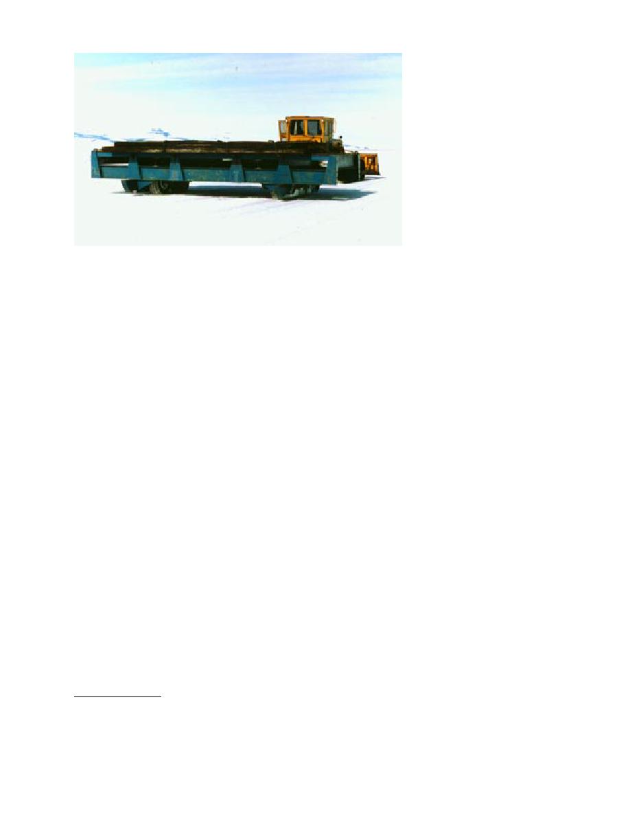
being fitted with either C-141
or C-130 main landing gear
wheels and tires. Tire configu-
ration on the proof cart is
nearly identical to an actual
aircraft. The cart has a flat
deck for placement of ballast
to a mass greater than the
maximum allowable load on
the main landing gear of the
aircraft (e.g., 142,400 kg or
313,300 lb for a C-141; 67,600
kg or 148,800 lb for a C-130).
Because of the very large
loads the cart carries, it was
designed to be flexible (i.e.,
Figure 49. Cart for proof rolling the Pegasus runway shown configured for C- most structural members were
bolted together) to reduce the
130 landing gear; ballast is steel plate.
possibility of component fail-
ure when the cart travels over
uneven terrain or breaks through the ice at one
allowable main landing gear loads and contact
tire station. During its initial use, the proof cart
pressures moving at very slow speeds or at rest.
was ballasted with large steel sheets that were on-
Contrary to what may be thought, landing im-
site in McMurdo for future construction of fuel
pact loads rarely exceed maximum static loading
tanks (Fig. 49 and 50a). The steel provided a con-
(O'Massey 1978). Upon impact during landing,
centrated source of mass, thus holding the center
the tire load is equivalent to the vertical kinetic
of mass to a modest level. Because of their flex-
energy only (related to aircraft sink speed), since
ibility, the large, thin steel sheets were difficult
the aircraft still has flying speed and thus the
and dangerous to handle during loading and un-
wings carry a lift force equivalent to the mass of
loading. Later, 1-m3 concrete blocks were use for
the aircraft. Maximum allowable aircraft loads
can be found in the aircraft maintenance manuals
ballast on the proof cart. These blocks were manu-
or from Jane's Defense Data publication, All the
factured in the U.S. and contained forklift pockets
World's Aircraft. It should be remembered that
at the bottom and a recessed lifting ring on the
9095% of the aircraft weight is carried by the
top to aid in handling. The blocks proved easier
main landing gear.
to place and secure on the cart, and it was easier
Proof rolling should cover as much of the run-
than the steel sheets to calculate and adjust the
way as is practical. In most cases, it should be
total ballast mass. However, the concrete blocks
possible to stress essential every square meter of
resulted in a much higher center of mass and
the runway by maintaining wheel tracks at a close
there was some concern for stability during op-
spacing (1 m or 3 ft). We recommend that a mini-
eration (Fig. 50b). Extensions were added to the
mum factor of safety (FS) of 1.25 (125%) be ap-
fore and aft "outriggers" to address this concern,
plied to the maximum allowable aircraft loads
but, the cart proved to be well balanced and the
and pressures. This is the same FS that is used for
extensions may not have been needed.
the McMurdo sea ice runway (Barthelemy 1992)
The proof cart is designed to "catch itself" on
and is estimated to be incorporated in the FAA
long steel runners if an ice failure occurs under a
design manuals for the thickness of conventional
wheel. When the cart is not in use, we parked it
airport pavements*. Proof rolling speed should
with wooden blocks under these runners to sup-
not exceed 5 km/hr (3 mph).
port the load, thereby reducing stress on the axles
We designed and built a cart (Fig. 49) for proof
and wheels and limiting pressure sinkage into
the ice. The proof cart was surprisingly easy to
rolling the Pegasus runway. The cart is capable of
tow. We found the proof cart most efficient to
pull with the 14G grader, since this provided a
comfortable ride for the operator and allowed a
*J. Scott, FAA Northwest Regional Pavements Specialist, per-
speed of 45 km/hr (23 mph) to be maintained.
sonal communication, 1995.
48


 Previous Page
