

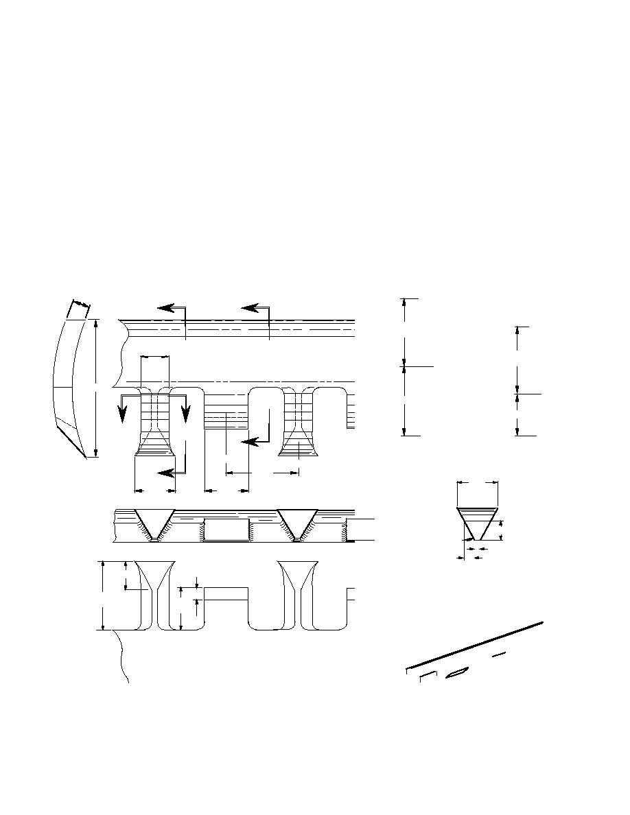
For finish grading, we used a different chisel-
There may be many days when weather con-
tooth design for the blade (Fig. 45) than was used
ditions reduce surface visibility to near zero
for initial grading. This blade appeared more ag-
due to diffuse light or blowing snow.
gressive than the one used for the first passes and
We found that the laser system was able to
was designed with an alternating tall- and short-
function and produce accurate grade even when
tooth pattern to assist in cleaning the surface of
the grader operator had great difficulty seeing
all debris. The geometry of the cutting teeth was
well enough to drive in a straight line. However,
similar to the rough grade blade with an included
angle of 42 and side relief angles of 41 (Fig. 46).
we found that the standard laser system trans-
mitter tower was not robust enough and began
However, the cutting teeth were considerably
vibrating under moderate wind conditions. This
longer, at 9.6 cm (3.8 in). The cleaning teeth had
an internal angle of 60, a height of 5.7 cm (2.2
caused the emitted laser plane to shift rapidly
and with such amplitude as to cause the grader
in.), and no side relief cut-out. The lower edge of
blade to go into convulsions. Thus, we constructed
the cutting teeth was flared to a width of 5.7 cm
a sturdy tower, mounted on skis for efficient
(2.2 in.) and was 4 cm (1.6 in.) closer to the ice
repositioning, on which to place the transmitter
than the cleaning teeth. For most of the runway,
(Fig. 44).
only one pass was required to arrive at the de-
19.1
A
B
97
(ref)
41.3
97
(ref)
193.7
97
57.2
C
C
B
C
L
C
L
101.6
A
(typ)
57.2
(ref)
57.2
60.3
(typ)
(typ)
19.1
41
7.9
16.7
14.3
38
97
All Dimensions are in millimeters
57.2
(typ)
(typ)
Figure 46. Geometry of individual chisel teeth.
43

 Previous Page
