that the water freezes quickly. Flooding the fill in
thermal and mechanical properties of the fill area
separate lifts may be necessary to allow the low-
will be very different than for the remainder of
est levels to freeze before more water is placed on
the glacial ice runway. This will make certifica-
top. In essence, the fill procedure should simulate
tion of the runway more difficult, and could eas-
an ice bath that is allowed to freeze rapidly, thus
ily cause the runway to be unusable because of
creating a mass of small-grained, randomly ori-
the failure of a small portion of the surface.
ented ice crystals. This will produce a very strong
filler for the low area.
Preparations for final grading
The surface of the frozen fill will be very rough.
During the final runway survey, benchmarks
We discovered that it was best to fill the basin with
should be set along at least one edge of the run-
snow and ice debris to an elevation slightly higher
way. These markers are best situated about 6 m
that the final anticipated grade. Thus, the surface
(20 ft) from the anticipated edge of the runway to
can be finish-graded along with the natural ice
allow equipment to operate along the flanks of
surface to provide a uniform texture for traffic.
the runway without the danger of damaging the
Few alternatives to a snow melter exist for gen-
markers. It may be necessary to keep the bench-
erating fill water at a remote site. If only a small
marks buried in snow to protect them from solar
amount of water is needed and the site is near an
heating. We buried all but a few centimeters of 1-
established camp, water may be transported to
m-long square timbers for use as benchmarks.
the site in containers via helicopter or oversnow
The markers need not be listed with actual eleva-
vehicle. In some cases, natural meltwater on the
tions, as long as the height of their tops are known
glacier at a nearby location may be utilized. This
relative to each other. For runway elevations, we
water may be transported or pumped to the site
used the base of the tower supporting the Pega-
via a hose. If a very large amount of water is
sus North AWS, situated just off the north end of
needed and a large capacity snow melter cannot
the runway. This master datum was arbitrarily
be used, establishing an in-situ water reservoir in
assigned an elevation of 30 m (100 ft) and all other
the snow (commonly called a Rodriguez well) it
elevations were listed with reference to this bench-
may be possible nearby in the glacier to supply
mark (actual elevation is about 6 m or 20 ft). We
freshwater needs (Lunardini and Rand 1995). If a
also placed flags along both sides of the runway,
camp will eventually be placed near the runway
set 7 m (23 ft) out from the edge and located every
site, such a well may be useful to supply its water
500 ft along its length. As is typical for runways,
needs in the future.
each 1000-ft multiple was numbered.
We caution against the use of seawater for use
After the final ice reconnaissance, core inspec-
in patching or filling. During the process of freez-
tion for weak ice, filling of any large depressions,
ing, seawater rejects its salt content, resulting in
and setting of benchmarks, the final grade for the
pockets of brine. This will only freeze at low tem-
runway will be decided. This decision will be
peratures and results in ice with significantly
based on minimizing the amount of grading neces-
inhomogeneous strength properties. Thus, the
sary by matching the natural topography as much
as possible (which also reduces the
amount of debris to be removed) in
North
South
0% Slope
order to produce a surface that meets
Relative Elevation = 96.2
0% Slope
pe
0.0025% Slo
Relative Elevation = 95.2
the roughness standards for the most
stringent smoothness requirements
0.3 m (1 ft)
associated with the aircraft that will
use the facility.
0
2000
4000
6000
8000
10000
Distance (ft)
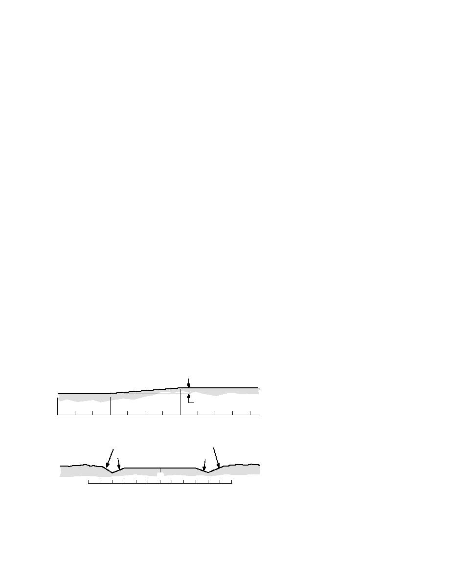
The final grade for the Pegasus
a
runway was set in three segments
(Fig. 43). Each of these segments was
East
West
2% Slope
3% Slope
designed to exactly match elevation
2% Slope
2% Slope
Natural Ice Surface
at their intersection points, although
Runway Surface
this would not have been necessary
C
L
(steps of as much as a few centime-
300
200
100
0
100
200
300
ters would not have caused any dis-
Distance (ft)
tress to the aircraft for which we
b
Figure 43. Final grade plan for the Pegasus runway.
designed). Two of our segments
41


 Previous Page
