EAGLE RIVER FLATS FY 00
80
image, dial the local ISP via the cell phone,
wards CRREL, the equipment that supports
and ftp the image to the ISP. The image would
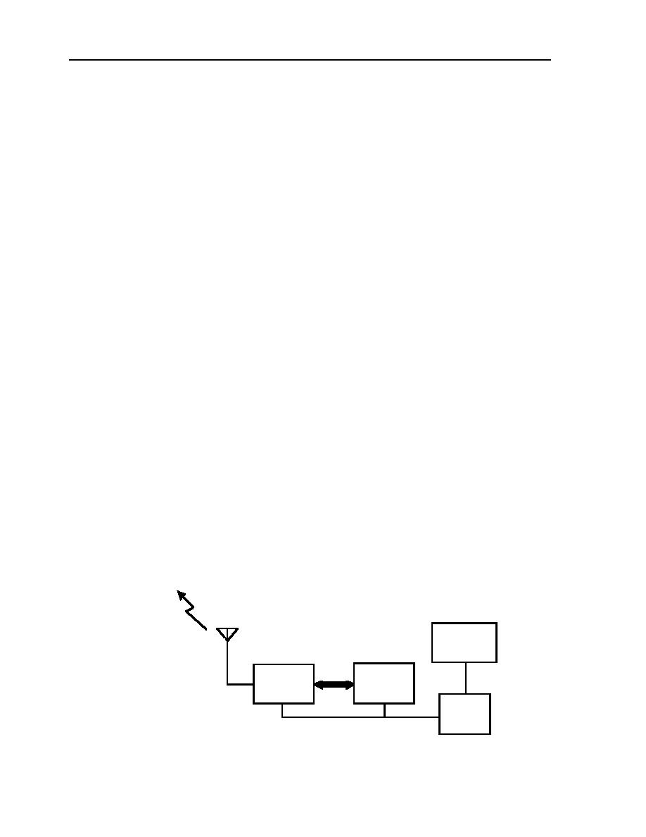
the AXIS 200+ is as follows.
then be transferred to the CRREL public ftp
The AXIS 200+ web camera is connected to
server. Once on the public ftp server, the im-
a Black Box Corporation model RF115 radio
age would be posted to the ERF web site.
frequency modem (RF115) via an EIA-232 in-
Though this design works well in an urban
terface. Solar panels, deep-cycle 12-V batter-
area with reliable cell phone coverage and AC
ies, and a 12-V charging regulator power this
line power, it is not reliable at a remote site
equipment. The AXIS 200+ web camera and
such as the Flats.
RF115 are housed in a Pelco environmental
The equipment used during the 1999 field
enclosure specifically designed for cameras.
season is designed to be powered by 120-V
This package is referred to as the remote site
AC. The only source of power at the remote
equipment (RSE) (Fig. III-5-2, III-5-3).
site is solar. Two 75-W solar panels and a
Hard-wire telephone service from the mili-
charging controller charged a bank of 12-V
tary Defense Switch Network (DSN) is avail-
batteries. The batteries in turn powered a 12-
able at Bravo Bridge (Fig. III-5-4). A US Ro-
V DC to 120-V AC inverter. The inverter's AC
botics telephone modem and RF115 modem
output powered the equipment. There was
identical to the one at the remote sites are lo-
not enough power available from the solar
cated on the bridge. The phone modem con-
panels and batteries, so the system eventu-
nects to the DSN, the phone and RF115 mo-
ally failed.
d e m s are connected by an EIA-232
connection, and omni-directional antennas at
both sites complete the data path.
Solar panels, a charging regulator, and
PROPOSED SOLUTION FOR THE 2000
deep-cycle 12-V batteries power the RF115
FIELD SEASON
modem and 12-V DC to 12-V AC inverter. The
To overcome the limitations of poor cell
inverter powers the US Robotics modem. This
phone coverage and the lack of AC line power,
equipment is housed in a NEMA-rated enclo-
it was decided that the RIS would use wire-
sure mounted to the northern abutment on
less radio technology and be powered by 12-
Bravo Bridge and is referred to as the base
V DC. The new approach uses off-the shelf
station equipment (BSE) (Fig. III-5-5, III-5-6).
components wherever possible, the exception
Data then flow via DSN to CRREL in
being a 12-V DC to 12-V AC power inverter
Hanover, NH (Fig. III-5-7). At the CRREL site,
designed and built at CRREL. Starting with
data are transferred through another US Ro-
the remote site (Fig. III-5-1) and working to-
botics modem and finally via a Digi Interna-
To Base Station
75-W
EIA-232
Solar Panel
Omnidi rectional
Interface
Axis 200+
Black Box
C amera
RF115
RF Modem
12-V DC
B attery
Storage
Figure III-5-1. Remote site equipment.


 Previous Page
