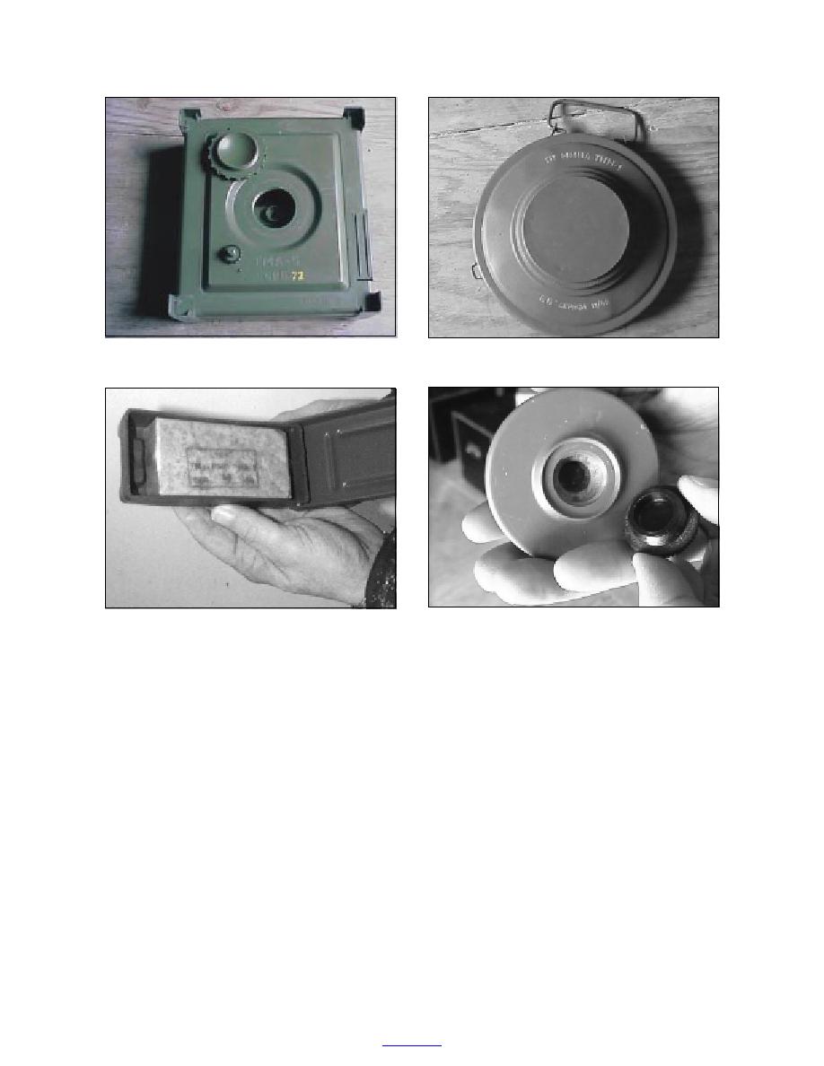
a. TMA-5.
b. TMM-1.
c. PMA-1A.
d. PMA-2.
Figure 1. Land mines.
were buried as described above. Burial depths for the
vidual mines of each type buried at the FLW site is con-
two sets of mines varied from 2 to 15 cm to their tops, in
fidential, as the site is being used for blind testing of
accordance with manufacturers' specifications (Table 6).
prototype land mine detectors.
All mines were buried manually according to manu-
Background characterization of soils at the
facturers' specifications; the mines were covered with
DARPA Electronic Nose Testing Facility
the same soil that was removed from the hole and, when
A series of soil samples was collected from areas at
possible, the vegetative cover was replaced and watered
least 5 m from the nearest buried mine to allow us to
to allow the mine scar to heal as rapidly as possible.
characterize the physical and chemical nature of the
A second set of mines was buried during the week
soils at the site. Soil samples were collected on three
of 13 April 1999. These mines included the Type 72, a
occasions by removing surface litter and collecting the
Chinese plastic-cased antitank mine containing 5.4 kg
top several inches of soil. Nine samples were collected
of 50%TNT:50%RDX; the VS2.2, an Italian antitank
in the first sampling event (samples designated 1
land mine containing 1.93 kg of Composition B (RDX/
through 9); 50 samples were collected during the sec-
TNT 60%/40%); the TS50, an Italian plastic-cased
ond sampling event (samples designated with numer-
antipersonnel mine containing 50 g of T4 (TNT/RDX);
als followed by a or b to indicate the upper 58 cm of
and the VS-50, an Italian plastic-cased antipersonnel
soil, a, or the next 58 cm, b); and 12 samples were
mine containing 43 g of pressed RDX. These mines
6
to contents


 Previous Page
