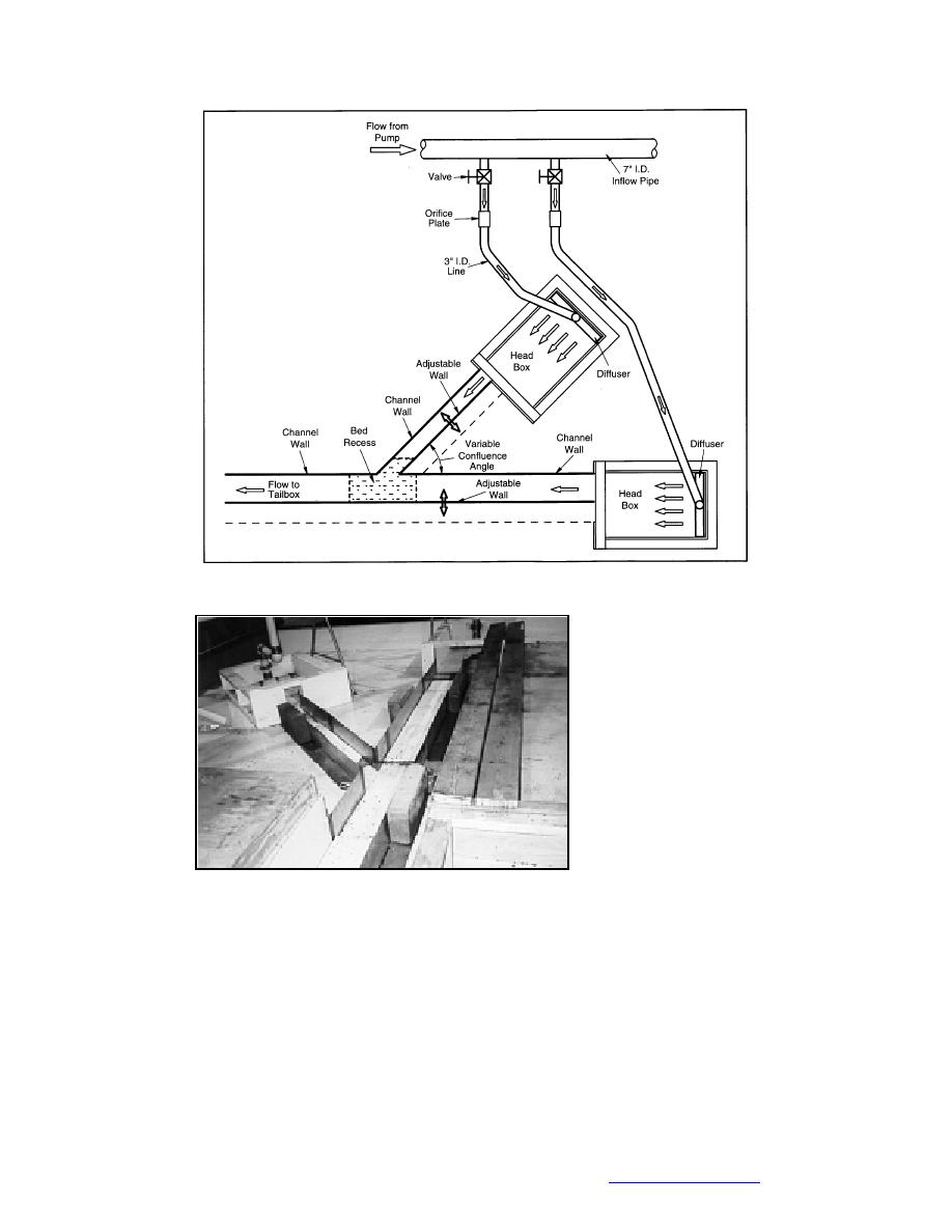
Figure 10. Layout of the jam process model.
channel downstream of
the confluence also was
sufficiently long that it
could re-establish uni-
form flow downstream
of the confluence. A tail-
gate positioned at the
model exit section con-
trolled the depth in the
channel.
The model channels
were constructed of sides
formed of folded sheet
Figure 11. View of the jam process model configured for a metal placed on a ply-
45 confluence.
wood channel bed or
base. The channel sides
were clipped together and anchored to the wood base by means of weights. This
construction technique provided a flexible design that facilitated easy and quick
re-arrangement of channel width and orientation. Most of the tests were conducted
with a flatbed confluence. For selected confluence cases, the tests were repeated
with simulated confluence bathymetry.
At the confluence, a piece of the wood bed was removable to create a recess in
which the bathymetric features of an alluvial confluence could be reproduced.
The features included those shown in Figures 10 and 11. Sand placed in the recess
was shaped to simulate the confluence bathymetry shown in Figure 4b. The sand
23
Back to contents page


 Previous Page
