seen, the fan and drill are used on the surface,
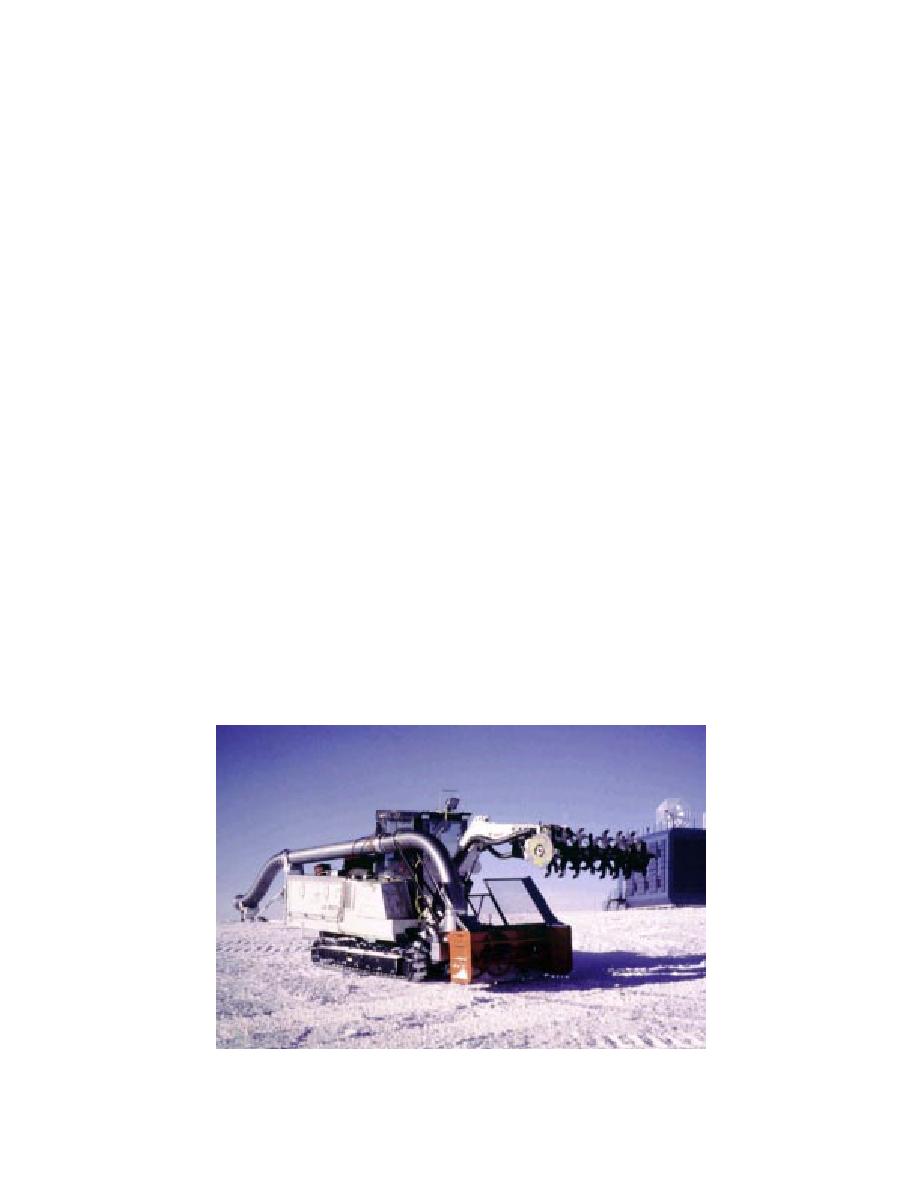
modified Melroe Bobcat 231 excavator with a
while the tunneler and chip conveyance ducting
Kubota BL2576 snowblower mounted to the front
are below the surface. The tunneler machines the
for chip removal (Fig. 8). The dipper stick and
face of the tunnel, depositing the chips at the base
bucket of the excavator have been removed, and
of the face. A snowblower, extensibly attached to
in their place a hydraulically powered rotating
the front of the tunneler, is fed into the chip pile,
shaft with a series of adjustable cutter arms was
centering and feeding the chips into the ejector
designed and installed for machining the tunnel.
pipe going over the tunneler. Behind the tunneler,
An electrohydraulic power pack was mounted on
a series of telescoping duct assemblies direct the
an extended frame behind the existing diesel mo-
chips to the transition sled, which is also attached
tor on the excavator for operating in confined
to a series of fixed-length vertical pipes. At the
spaces. The tracks on the excavator were extended
surface, the vertical pipes are attached via a flex-
60 cm to the rear of the machine to lower the
ible hose to the centrifugal fan (blower), which
ground pressure and balance the machine. A frame
powers the chip conveyance system and blows the
was built for the attachment of the snowblower to
chips clear of the area. The drill rig drills the holes
the tunneler to allow the snowblower to be lifted
used for the vertical chip conveyance tubing and
and lowered, as well as extended and retracted,
the power cord that supplies power from the sled-
to aid in accessing the debris pile at the base of the
mounted generator module on the surface to the
tunnel face during tunneling operations. An ex-
tunneler. The generator also provides power to the
tending chip ejector system was designed to bring
centrifugal fan. The workshop is used as a base of
the milled debris from the snowblower to an at-
operations and to make minor repairs to the equip-
tachment point at the rear of the machine. Tilt in-
ment.
dicators in the cab and on the boom of the tun-
neler provide the operator with information on the
pitch and roll of the tunneler, as well as the angu-
Tunneler
When the tunneling project was initiated in
lar position of the boom.
January of 1992, less than a year and a half was
The tunneler employs a transverse rotational
available to develop the concept, design and fab-
machining system for milling the face of the tun-
ricate the system, and test the equipment before
nel. This system, which is called the "cutting
shipment. Because of this time constraint, modi-
drum" or just "drum," is actually made up of a
fying existing equipment was chosen over the
series of diametrically opposed cutters on axially
development of new designs for most of the sub-
mounted cutter arms (Fig. 9). These arms are
systems. The basic tunneler concept is based on a
mounted to hubs along the axis of rotation such
Figure 8. The tunneling machine.
6


 Previous Page
