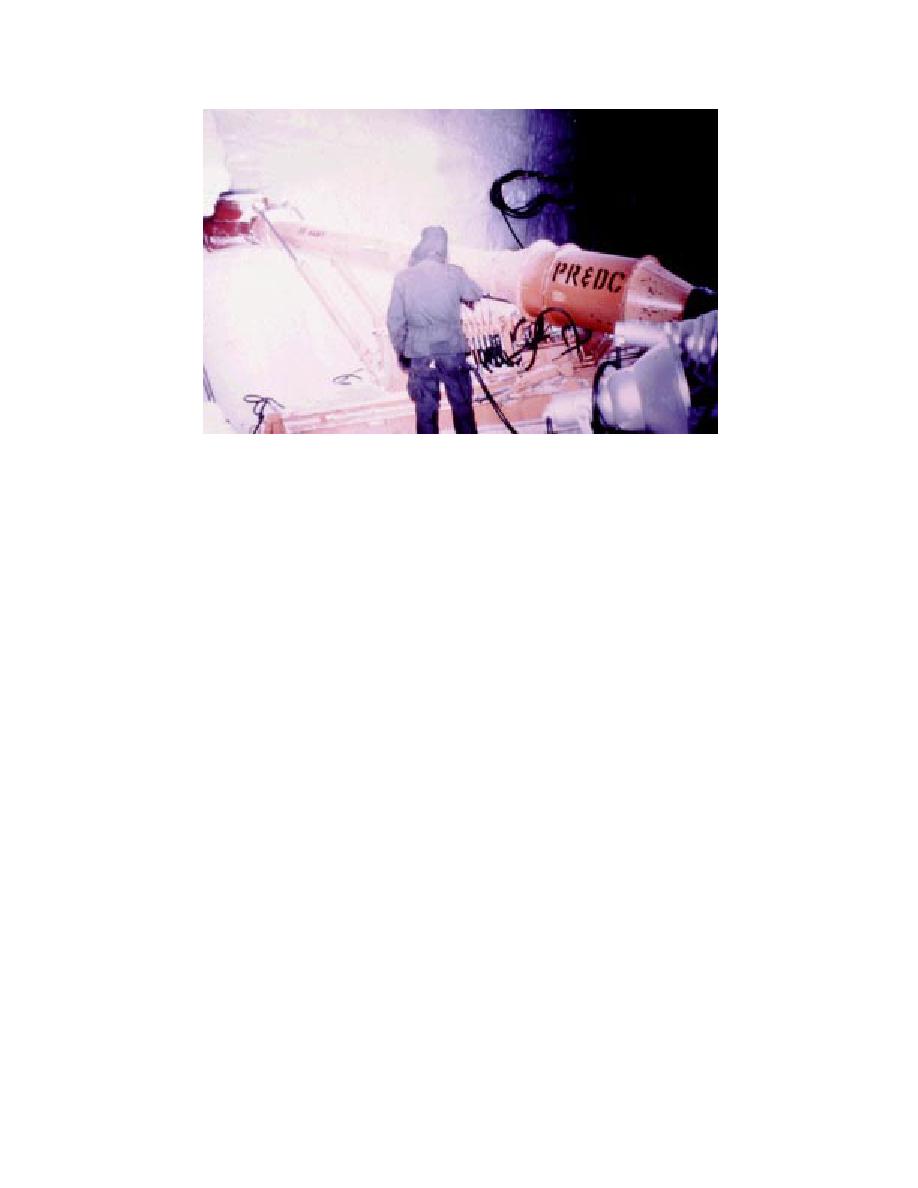
Figure 5. The Russell Miner (Greenland, 1965).
gated. In 1963, CRREL developed the Russell
conducted without the hazards of wind, drifting
Miner, a machine specifically designed for tunnel-
snow, and extreme cold, make the concept highly
ing in snow and ice (Fig. 5). Although somewhat
desirable.
effective at machining snow, the two-phase pneu-
Before NSF accepted the unlined tunnel con-
matic transport system used by the miner, which
cept, CRREL ran a series of finite element model
consisted of a series of vane-axial fans, was prone
(FEM) analyses to determine the theoretical
to freeze up and breakdown. Tests in Greenland
strength and deformation of the tunnel for vari-
at Camp Century in June of 1965 demonstrated
ous snow conditions (Sodhi et al. 1993). These
the crippling flaw of the system, the tendency of
simulations were run at two tunnel roof depths,
the fans to ice up and clog. Much development
4.6 and 6.1 m. The model took into account both
work was needed to enable the system to operate
the snow load and the static load imposed by a
effectively, and the program was dropped. How-
very heavily loaded C-130 aircraft (94 t). Snow
ever, very valuable lessons were learned over the
properties were taken from Mellor (1975) and Gow
course of the Russell Miner's development, les-
and Ramseier (1964). Both cases indicate the tun-
sons that were directly applicable to the South Pole
nel will not fail, but a 6-m minimum overburden
tunneling concept.
was recommended because of the uncertainties
inherent in all mathematical models.
In November of 1991, CRREL engineers ran two
different series of tests at the South Pole to help
THE UNLINED TUNNEL
verify the model through the collection of empiri-
cal data (Fig. 6). The first series of tests entailed
As previously noted, the concept of an unlined
tunnel is not new. The unlined tunnels of Camp
the construction of a "half-scale" model of the tun-
nel, 1 2 m in cross section, 13 m long, and 3.3 m
Tuto, Greenland, machined into ice at the face of
below the surface of the snow. A bulldozer with a
the ice cap with heavy mining equipment, were
ground pressure in the 43- to 47-kPa range was
completed over 30 years prior to the inception of
trafficked over the tunnel a distance of 7.6 m from
this project (Abel 1961). The advantages of the
the entrance. No failure occurred under this con-
unlined tunnel include construction using native
dition, which simulates a 2- 3-m tunnel 6.3-m
materials (ice and firn), the ability to tunnel at
depths greater than those to which cut-and-cover
deep under a 98-t load. The tunnel roof was raised
tunnels are restricted, simplicity and flexibility of
to 2.3 m below the surface, and another was test
design, and ease of maintenance. As with any tun-
run, resulting in a crack forming in the tunnel ceil-
nel, the ability to run utilities in a protected envi-
ing. This corresponds to a tunnel depth of 4.2 m.
ronment, where maintenance and repair can be
The crack, although not predicted by the model,
4


 Previous Page
