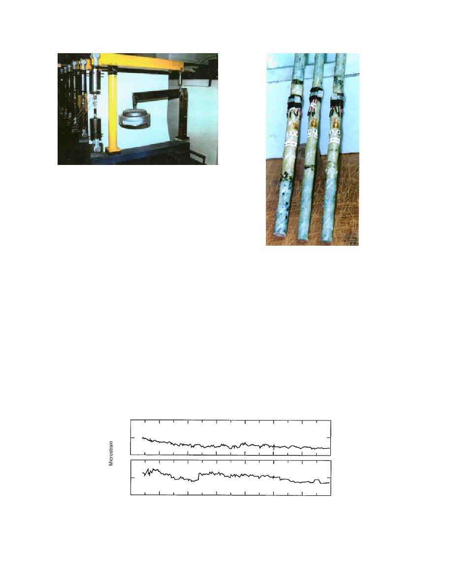
Figure 59. Creep test platform with six creep test
fixtures.
Each composite rebar was instrumented with
electrical foil strain gages to measure both the lon-
gitudinal and diametrical strains (Fig. 60). Even
though only longitudinal strains were of interest
in this creep study. The gages were centrally
located along the length of each specimen and dia-
Figure 60. Strain gage instru-
metrically opposite to each other. Each longitudi-
mentation on the test specimens.
nal gage was axially aligned with the fiber direc-
Test specimens shown removed
tion and positioned so as not to interfere with the
from the test fixture after the
spiral wrapping of the rebar. The gages had an
test was over.
effective length of 1.58 mm (0.062 in.), 350-ohm
resistance, and were temperature compensated for
The deadweights were adjusted to tension each
steel. The gages were bonded to the rebar surface
of these rebars to about 50% of its ultimate
according to the manufacturer's recommended
strength, as specified by the rebar manufacturer.
procedure. To avoid modifying the rebar speci-
In order to monitor temperatures, a thermo-
men resin, as per the gage manufacturer's instruc-
couple was attached to each rebar. Once the ten-
tions, the gages were cured overnight at room tem-
sion for the rebar was fixed, the apparatus was
perature. No elevated temperature curing was
not disturbed. For the room-temperature tests,
attempted. For measuring strain, each gage was
temperature and strain readings were taken once
put in a full-bridge configuration and initially bal-
a day for 1800 hours (75 days). The strain data
anced in a switching and balancing unit. All sub-
are shown in Figures 61a and b for the 12.70-mm
sequent readings were referenced to this initial
(0.5-in.) and 15.88-mm (0.625-in.) bars, respec
balance.
1.20 103
(a) 0.5 (a)rebar
in
1.15
1.10
1.30
(a) 0.625(in)rebar
b
1.25
1.20
31 Jul 91
20 Aug
9 Sep
29
19 Ot
8 Nov
28
18 Dec
Period of Test
Figure 61. Records of room-temperature creep strain for (a) 12.70-mm (0.5-in.)
diam. rebar, and (b) 15.88-mm (0.625-in.-) diam. rebar.
44


 Previous Page
