Table 15. Mechanical characteristics of composite rebars.
1.85 g/cm3 (0.067 lb/in.3)
Density
Ultimate tensile strength
117.9 MPa (17,098 psi)
54.206 GPa (7.86 106 psi)
Tensile modulus
9.9 10-6 mm/mm C (5.5 10-6 in./in. F)
Coef. of thermal expansion
Matrix
Derakane 411-45 polyester resin
Fiber
E-glass
Spiral fiber pitch
190.5 mm (0.75 in.)
4.2 in.
21 in.
Strain Gauge
1.5 in.
15 in.
Weight
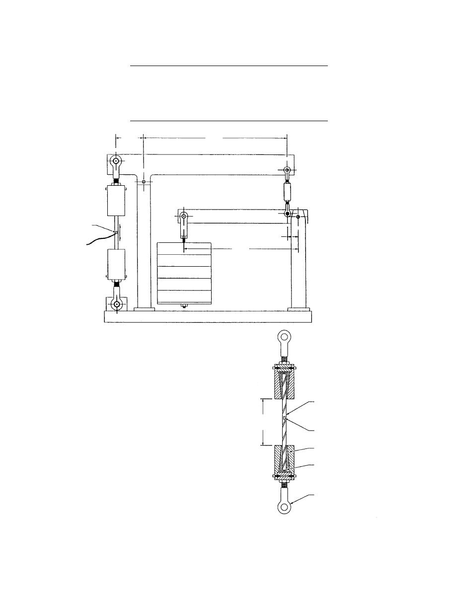
Figure 57. Deadweight
creep test fixture.
tics of these bars, as provided by the manufac-
turer, are given in Table 15.
To conduct the creep tests, the deadweight
creep test fixture shown in Figure 57 was designed
and fabricated. The gripping mechanism is shown
in Figure 58. The fixture provided a mechanical
advantage of approximately 50 to 1. Six of these
creep test fixtures were mounted on a common
Protruded Fiberglass Rebar
base frame (Fig. 59).
Initially, six fiberglass composite rebars made
6 in. Test
by a single vendor were selected for the tests. The
Length
Strain Gauge
rebars were obtained in 12.70, 15.88, and 19.05
mm (0.5, 0.625, and 0.75 in.) nominal diameters,
Gripper Housing
with a spirally wrapped glass fiber strand, wound
with an approximately 19.05 mm (0.75 in.) pitch.
Epoxy
The entire rod was redipped in resin and then
cured to obtain an irregular wavy but drip, sur-
face to promote adhesion to the concrete. For fix-
ing on the test jigs, the 19.05-mm- (0.75-in.-) diam.
Turnbuckle
rebar specimen proved to be the most difficult to
be gripped and was finally rejected from the test
batch. Only 12.70-mm- and 15.88-mm- (0.5-in.-
Figure 58. Details of the gripping mecha-
and 0.625-in.-) diam. bars were finally tested.
nism of the creep test fixture.
43


 Previous Page
