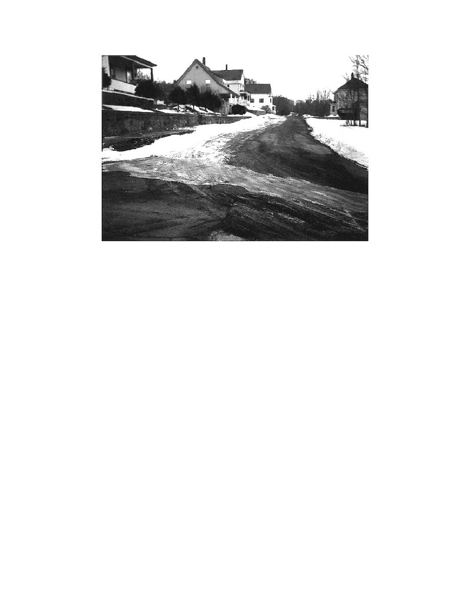
Figure 17. Wentworth Street showing clear roadway over insulated pipeline while rest
of road has light snow cover.
the surface is warming and the shield prevents
cern for differential surface icing prevented the
the transmission of that warming energy deeper
Wentworth Street shield from being set closer to
into the soil, thus causing higher temperatures
the surface. Differential surfacing icing is a possi-
above the shielded area, melting the surface
bility during certain meteorological conditions
snow. These conditions could also be enhanced
when there is insulation below the surface,
by the different thermal properties between the
because the insulation both retards the natural
backfill and the parent material.
geothermal heat flux from reaching the surface
The use of a utility line frost shield should be
and retards heat transfer from the soil above the
driven by the economics of the situation. Bal-
insulation to the soil below it. Under freezing
anced against the extra cost of buying and install-
conditions, if moisture is present at the surface, a
ing the shield are the decreased excavation costs
surface frost may form on the roadway. The
both for the initial installation and for future
width and location of most utility lines means
maintenance. If it is desirable to use a shield, then
that any surface icing caused by a utility line
the numerical modeling procedure shown here
shield would probably be less than 0.91 m (3 ft)
can offer insight into a proper design.
wide and would run along one side of the street.
When designing a shield, designers must de-
A road may also develop surface icing during cer-
termine the amount of risk they are comfortable
tain meteorological conditions even with no insu-
with. The advantage of an FE procedure is the
lation present. A study by Sweden's National
Road and Traffic Research Institute (VTI) (1981)
quantifiable output, e.g., time to freeze, that is
discusses pavement icing on both insulated and
available as a tool to assess that risk.
uninsulated roads.
There are also conditions where the roadway
RECOMMENDATIONS
over the insulated portion of the shield is bare
and the surface over the uninsulated section has a
The finite element procedure of designing frost
snow or frost covering. Figure 17 shows just such
shields should be used where designers are con-
a condition at the Wentworth Street site. The
fronted with the need to lay water or sewer lines
righthand side of the street has the shielded pipe
within the frost penetration depth. It can provide
beneath it and is free of snow cover, while the left
very useful, accurate, and quantifiable output to
side still has snow on it. This is probably because
assess various shield designs.
17


 Previous Page
