Open Files
Input Initial Conditions
Increment
Water/Time Step
Input
New Boundary
Conditions
Iterate
Ice Stability Check
All
Reaches
Yes
Stable
Iterate
No
Solve
Ice Equations
Increment
Ice/Time Step
Solve
Water Equations
Write Output
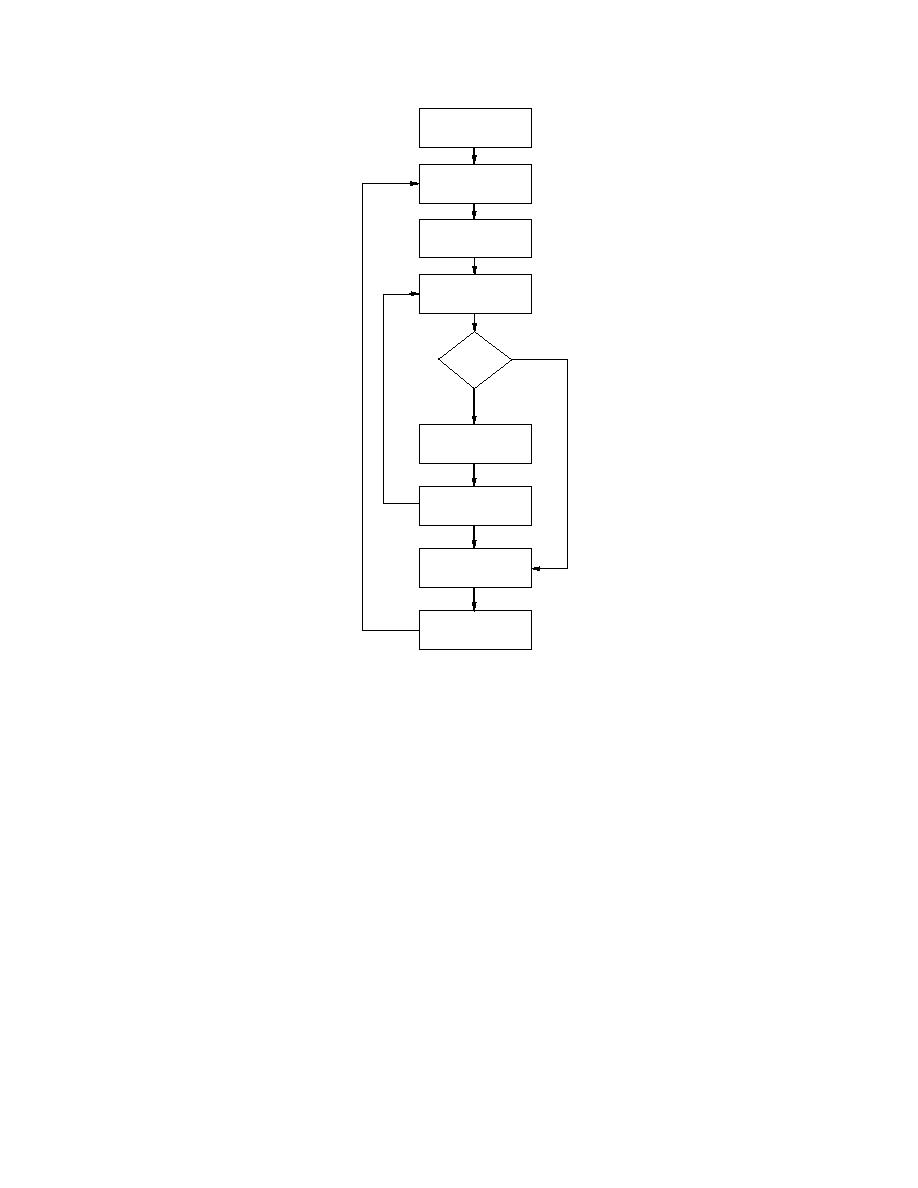
Figure 34. Block diagram for the
loosely coupled solution scheme.
above and two below the main diagonal. Two equations for each reach relate the
2N (water or ice) unknowns. A single boundary condition at the upstream and the
downstream ends is required to close the system.
The block diagram for the loosely coupled solution scheme is presented in Fig-
ure 34. The initial conditions are read, the timer incremented, and boundary condi-
tions for the new time step obtained. The ice variable solution can have a different
time step than the water variable solution and is specified as an even fraction of the
water time step. This procedure is needed because the ice variables can change
faster than the water variables, especially when moving ice stops and thickens. The
ice cover stability is checked, the ice variable coefficient matrix is computed and
solved, tolerances are checked, and the ice variables are reset for the next ice time
step. If the entire ice cover is found stable, the ice variables are simply reset and the
ice time step incremented. Following the correct number of ice time step calcula-
tions, the water coefficient matrix is computed and solved, tolerances checked, and
the water variables reset. This solution mode is included as a comparison to the
fully coupled mode because there are currently no existing formulations that are
fully coupled.
53


 Previous Page
