ity measurement is that the frequency shift
0
obtained must be resolvable by the radar system.
In a CW Doppler system a single-frequency RF
carrier is transmitted toward the target at an obli-
5
que angle (Fig. 1). When the target is moving, the
backscattered signal exhibits an apparent shift
from the transmitted carrier frequency--higher if
10
movement is toward the radar and lower if it is
away from it. A low-level sample of the transmit-
15
mixed with the backscattered signal received. The
mixing process results in four frequencies: the
reference signal, the backscattered signal, and the
20
sum and difference of these frequencies. The dif-
ference frequency resulting from the mixing is the
25
of the target. The velocity v (m/s) of a moving tar-
get is obtained as (Roddy 1984)
40
20
0
20
40
λfd
θ
v=
(2)
2cos α cos β
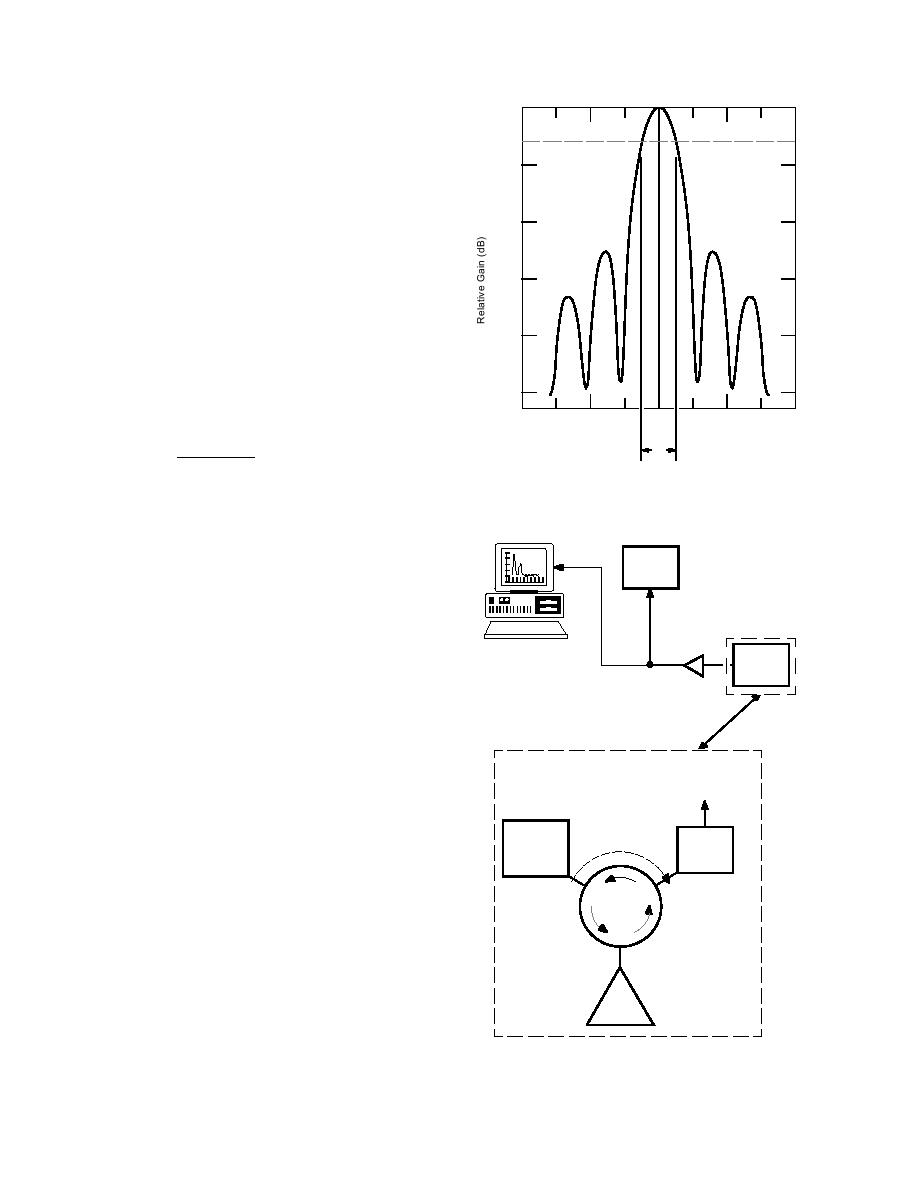
Figure 2. The 3-dB beam width of a radar antenna.
where λ = wavelength (m) of the RF source
α = horizontal off-stream angle as shown
in Figure 1.
β = vertical look-angle measured down-
DAT
ward from the horizontal
Recorder
The wavelength and frequency of the source are
related as λ = c/fs, where c is the speed of light in
a vacuum (3 108 m/s). The power transmitted
Computer
Doppler
with
by the radar is not localized at the point on the
Radar
DSP Card
System
target surface aligned with the center of the an-
Audio
tenna boresight. Instead, it is distributed over an
Amplifier
area on the surface, with the incident power di-
minishing with distance from the boresight. The
3-dB beam width shown in Figure 1 is defined as
To Audio Frequency
the angular width of the radar beam at the half-
Data Acquisition and
power points, as illustrated in Figure 2.
Processing Hardware
The Doppler radar implementation used for
these experiments (Fig. 3) includes a radar front-
ReferenceSignal
Single
Leakage Path
end and a data acquisition and processing com-
Frequency
Mixer
puter. The radar front-end system (expanded in
Source
Fig. 3) consists of a standard gain horn antenna
Port 1
Port 3
that is connected via a circulator to a single-fre-
Circulator
quency, continuous-wave microwave source and
a single-ended diode mixer. The circulator is a fer-
romagnetic device that directionally commutates
Port 2
power on a sequential port-to-port basis and per-
mits simultaneous noninterfering transmission
Horn
and reception of the radar signal using a single
Antenna
antenna. Ideally, all power entering port 1 is
transmitted to port 2, power entering port 2 is
Figure 3. Fundamental components of the Doppler
transmitted to port 3, and power entering port 3 is
radar system with an expanded view of the front-end.
transmitted to port 1. Port-to-port isolation in the
3


 Previous Page
