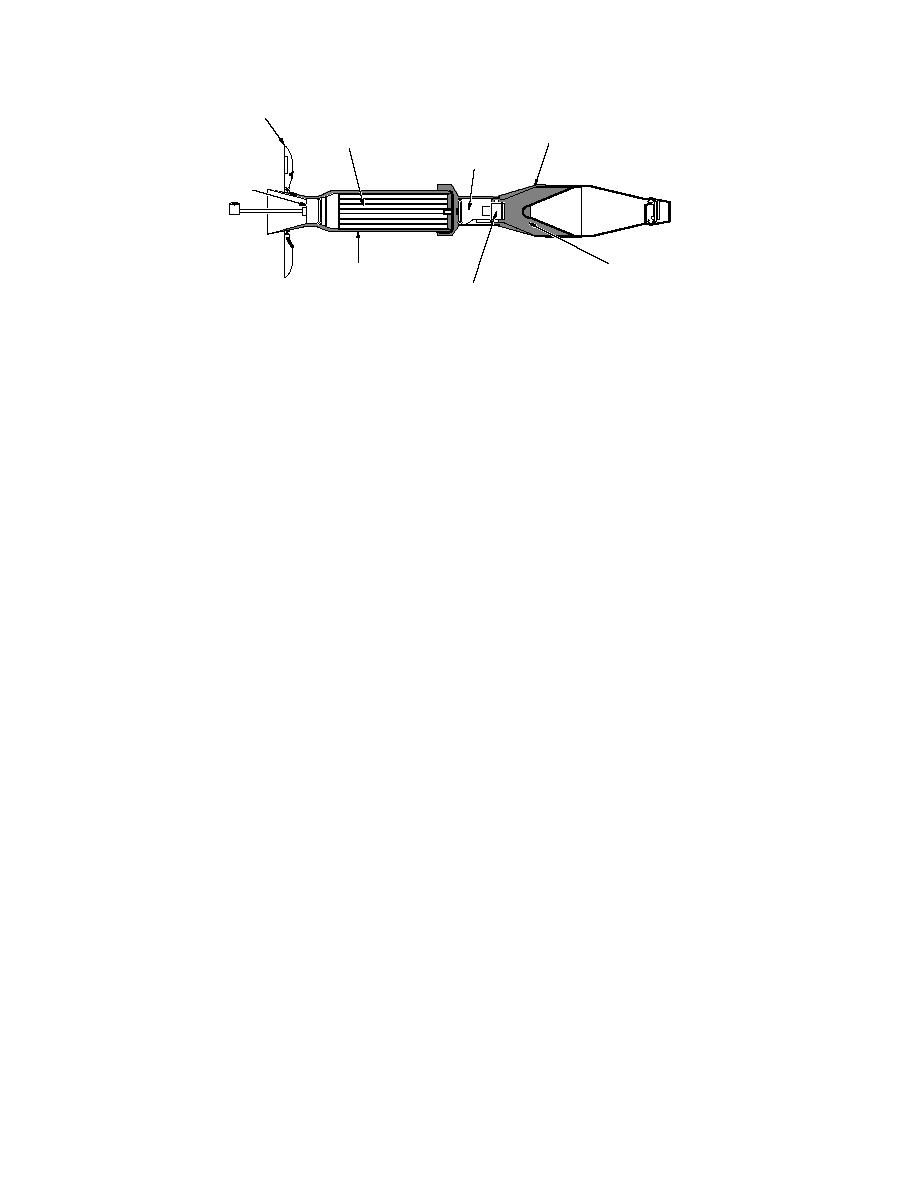
Folding Fins
Warhead Body
Propellant Charge
Fuse
Motor Body
Explosive
(Octol, 70:30 HMX:TNT)
Comp A5 Booster
(RDX)
Figure 4. 66-mm M72 LAW rocket.
samples and the manner of preparing com-
ence at a similar site at CFB-Valcartier (Jenkins et
al. 1997a), four 5- 5-m sampling grids were
posites to better provide representative
samples for specific areas within the impact
established near the tank target (Fig. 5). Grid A
ranges.
was just in front of the tank (between the tank and
Specify analytical protocols to estimate con-
the firing positions), with its edge up against the
centrations of target analytes within these
side of the target vehicle. Grid B was positioned 5
samples.
m to the left of the target (as you face the target from
the firing positions) and encompassed a 25-m2 area
Provide statistical criteria to use when com-
ranging from 5 to 10 m from the target. Similarly,
paring results to the cleanup levels estab-
grid C was placed 10 m behind the target and grid
lished for impact ranges at Fort Ord.
D was 15 m to its right, as shown in Figure 5.
Within each grid, a diagonal line was drawn from
The third objective was to evaluate a draft pro-
the left front corner to the right rear corner. Two
tocol that we have developed for conducting pre-
positions were chosen along this diagonal--one-
liminary site assessments that can be used to
third and two-thirds of the distance along it. At each
prepare a full-scale sampling plan that is tailored
position, two sampling points were selected--0.5
to the specific contamination profile at the site
m to each side and perpendicular to the diagonal.
under investigation (App. A). In addition, we
In this way, four sampling points were established
intend to provide the Sacramento District with
within each grid (Fig. 6). Our numbering system for
information, developed since the 1994 study was
the four samples from the grid nearest the target is
completed, that might be relevant to this problem.
1-44-1 through 1-44-4. Likewise, samples 1-44-5
through 1-44-8 are from the grid offset 5 m to the
left of the target, samples 1-44-9 through 1-44-12
EXPERIMENTAL METHODS
are from the grid 10 m behind the target, and
samples 1-44-13 through 1-44-16 are from the grid
Sampling design
15 m to the right of the target.
The following sampling design was developed
to evaluate the relationship between residual con-
Location R44
taminants at the inland ranges and the placement
At range 44, one 5- 5-m background grid, des-
of tank targets. Ranges 44 and 48 were selected
ignated R-44, was located behind the major firing
(Fig. 2b) because they had the highest concentra-
position so that it would have no residues origi-
tions of HMX, RDX, TNT, 4-AmDNT, and 2-
nating from nearby detonations. This location
AmDNT reported in the 1994 study.
served as a background sampling area. Four sam-
pling points were established in grid R-44 as
Location 144
described for 1-44 above.
In range 44, the area having the highest concen-
tration of explosives residues in the 1994 study was
Location 148
selected for further investigation (Fig. 2b). This
Three sampling locations were established
area is adjacent to a tank target that was exten-
within range 48. The first, designated 1-48, was
sively used, as evidenced by the large amount of
adjacent to a tank target. Four grids, each with four
debris located around it. This area is designated
sampling points, were established for 1-48 in an
as location 144. Based on our previous experi-
5


 Previous Page
