design of these systems was completed in early
Inc. 1989). These findings generally agreed with
1991 and a construction contract was awarded in
those obtained at a site located approximately
April 1991 (Anonymous 1991). Construction
0.5 miles (0.8 km) to the northwest of the CFR
started in late April 1991, but exceptionally high
area (Dames & Moore 1992), where monitoring
groundwater resulting from heavy snowfalls dur-
over 12 months indicated a gradient of 1.1 to 4.2
ing the winter of 199091 delayed completion.
ft/mile (0.2 to 0.8 m/km) to the westnorthwest.
Because of the construction delay, the facilities
Four groundwater monitoring wells, denoted
began to operate during the first two weeks of
B1B4, were installed at the site in 1989, and
August 1991.
during 1991, an additional five monitoring
wells, denoted IG1IG3 and DEC1 and DEC2,
were installed in conjunction with the construc-
Landfarm
tion of the infiltration gallery. In 1992 three wells,
Design
denoted TR1 through TR3, were placed with
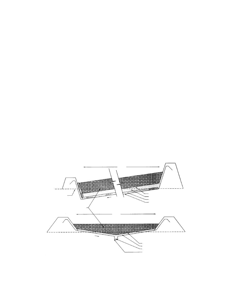
The landfarm is a lined, bermed area that is
individual sampling tubes at 1-ft (30-cm) inter-
190 by 230 ft (58 by 70 m). The liner is 60-mil
vals along the length of the well casing. An addi-
(1.524-mm-thick) high-density polyethylene
tional well, PTAN, was installed approximately
(HDPE) and is protected at the top and bottom
750 ft (229 m) up-gradient of the site. During
by 12-oz (4.07-g/m2) fabric. A 1-ft (30-cm) layer
summer 1991, two groundwater pumping wells,
of filter rock covers the liner to aid drainage. To
IGWW and LFARM, were installed at the site in
prevent clogging, the filter rock is separated from
conjunction with construction of the remediation
the overlying contaminated soils by nonwoven
facilities (Fig. 1c).
geotextile separation fabric (Fig. 3). A system
was installed inside the liner to collect and recir-
culate leachate. Berms are sufficiently high to
FIELD REMEDIATION PROCEDURES
contain projected annual precipitation. Leachate
The treatment technologies used at the site
recirculation is routed through a mixing tank for
were two ex-situ methods, landfarming and a
nutrient additions and then through spray irriga-
recirculating leachbed, and an in-situ method,
tion lines on the surface of the landfarm site. The
an infiltration gallery, for saturated soils. The
soil surface under the liner is sloped to ensure
230 '
SEPARATION FABRIC
ORIGINAL GROUND
FILTER ROCK
1%
UNDER DRAIN
LINER SYSTEM
CONTAMINATED SOIL
190'
2%
SEPARATION FABRIC
FILTER ROCK
UNDER DRAIN
NO SCALE
LINER SYSTEM
a. Construction specifications.
Figure 3. Landfarm (1 ft = 0.3048 m).
5


 Previous Page
