confluence geometries besides that of the Missis-
more or less stable ice cover, and its ice, by
sippi and Missouri rivers. Channel widths b and
and large, seems to be retained at the several
alignments α and β can be readily altered. Flow is
lock and dam facilities upstream of the
recirculated by means of a pump, whose discharge
confluence.
The main difficulty produced by ice moving
splits in two lines to the headbox of each channel.
An overflow tailgate at the downstream end of the
through the confluence is blockage of tow-
model is used to regulate water levels in the model
barge traffic up and down the Mississippi on
(see Fig. 10).
its way to and from the Illinois River. Tows
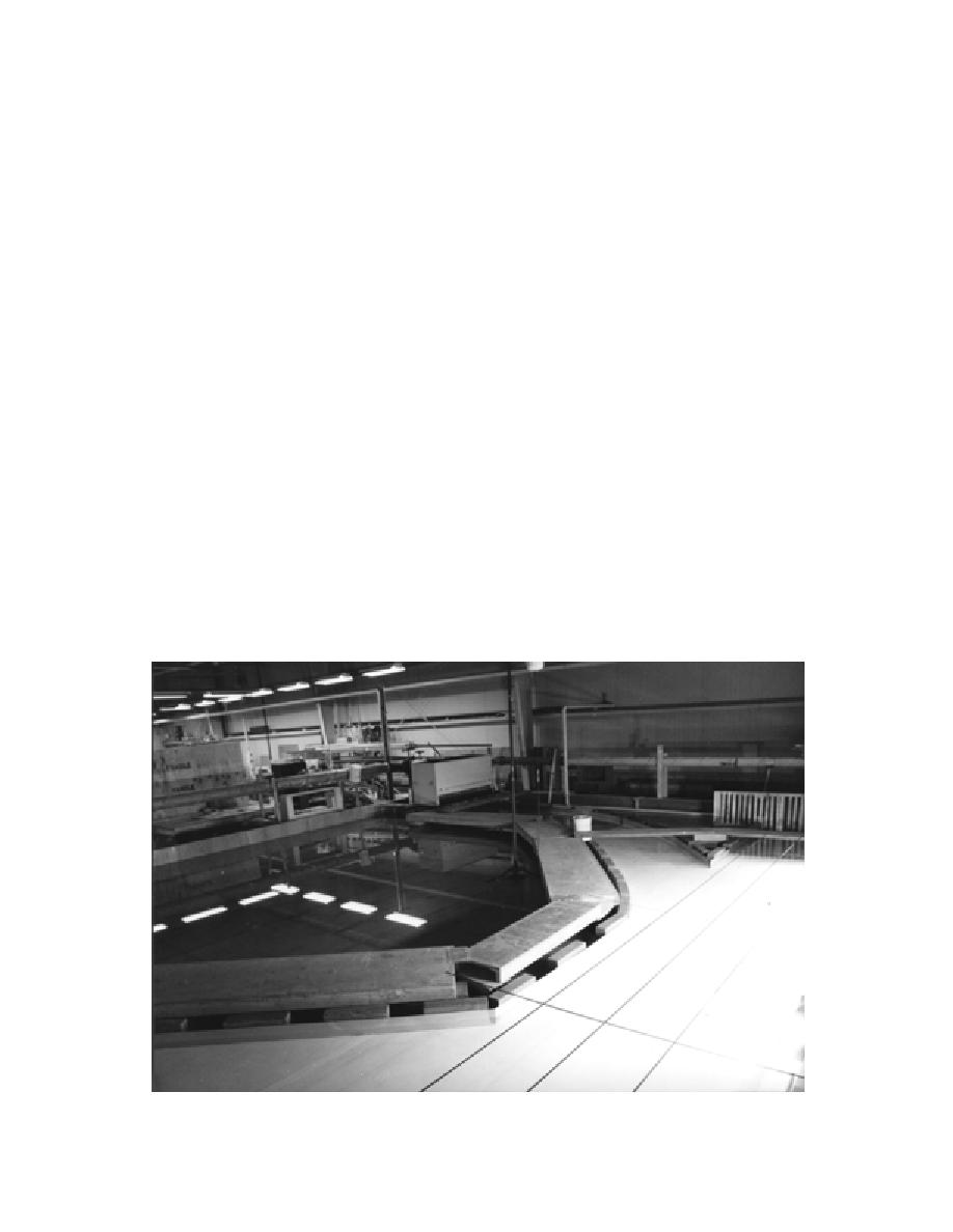
The model simulated a 4830- by 4830-m area of
have great difficulty moving through the ice
the confluence at horizontal and vertical length
because of lateral pressures exerted through
scales of 1:500 and 1:100, respectively.
the ice. Those pressures tend to pinch the tows
Three bathymetries of the confluent channels
and close tow tracks opened through the ice.
were simulated for the tests:
Also, some docking facilities along the Mis-
sissippi River's bank at the confluence have
Rectangular channel cross sections.
been damaged by ice.
Alluvial-bed bathymetry approximately that
The Corps engineers were pondering the fol-
of the MississippiMissouri confluence.
lowing actions to address difficulties in ice
Alluvial-bed bathymetry with border ice
movement through the confluence--remov-
approximately simulating the "accumula-
ing the point bar along the inner side of the
tion" condition depicted in Figure 9 for the
confluence, realigning the confluence, and
confluence.
blocking leakage of flow along a small slough
behind the point bar. The point bar and small
These represent an ascending order of bathy-
metric complexity that has helped determine the
slough are evident in Figure 9.
effects of channel bathymetry on ice movement
through the confluence. The rectangular channel
Hydraulic model configuration
section is the basic case of two confluent rectan-
The model comprises a large plywood tray, 9.5
gular channels and the simplest configuration for
by 9.5 m in plan dimensions (Fig. 8). The tray may
numerical simulation. The addition of alluvial bed
contain model confluences simulating a range of
Figure 10. View of the hydraulic model's alluvial bed bathymetry.
15


 Previous Page
