Table 2. Temperature sensor locations under pave-
FIELD INSTRUMENTATION
ment surface (cm).
AND TESTING PROGRAM
Sensor
TC1, TC2 (CWA)
In the summer of 1985, several locations along the
no.
TC1, TC2 (OCA)
TC3 (CWA)
TC4 (CWA)
airport runways and taxiways were instrumented with
moisture sensors and copper-constantan thermocouples
1
30.5
30.5
30.5
2
45.7
45.7
45.7
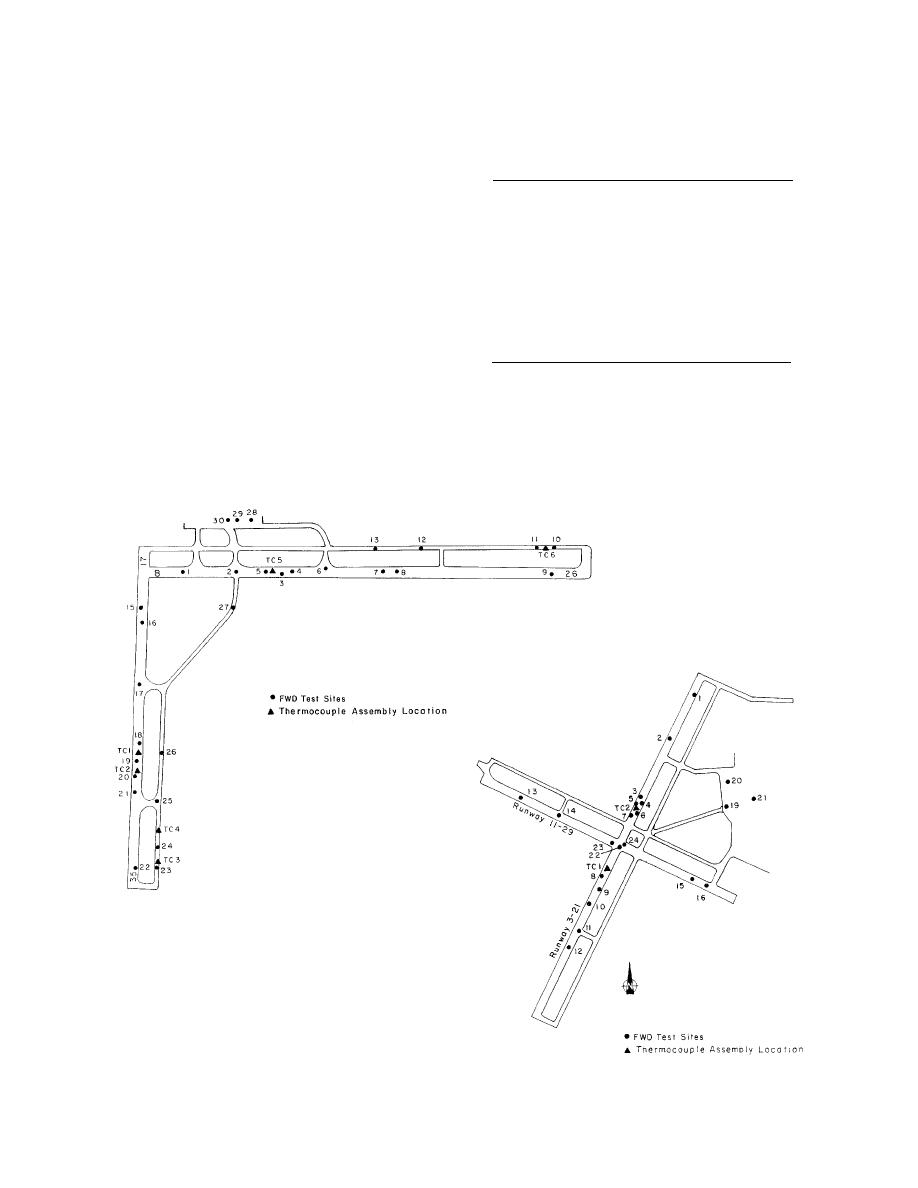
as temperature sensors. At CWA, six locations were in-
3
61
106.7
61
strumented for temperature measurement (Fig. 4a). At
4
91.4
137.2
91.4
OCA, there were two temperature measurement sites
5
121.9
167.6
121.9
(Fig. 4b). With a few exceptions, thermocouples were
6
152.4
198.1
152.4
7
182.9
228.6
182.9
placed to depths of approximately 5 m below the pave-
8
213.4
259.1
213.4
ment surface. The spacings of the sensors are given in
9
243.8
289.6
243.8
Table 2. At TC4, the hole could not be held open past
10
304.8
350.5
259.1
2.5 m from the surface.
11
365.8
411.5
137.2
12
487.7
472.4
106.7
The temperature measurements were made periodi-
cally by airport personnel during the winter months and
by CRREL personnel during the FWD testing period in
was conducted at selected sites at the two airports.
the spring. The measured temperatures at the two air-
The FWD test sites covered a large area of the airports
ports are given in Janoo and Berg (1996).
and included both AC and PCC pavements. As men-
In the spring of 1986, non-destructive testing using a
tioned earlier, the analysis presented here is for only
Dynatest 8000 Falling Weight Deflectometer (FWD)
the PCC slabs. Deflection measurements were made
a. Central Wisconsin Airport.
Figure 4. FWD, temperature and moisture sensor locations.
b. Outagamie County Airport.
4


 Previous Page
