APPENDIX E: AS-BUILT LAYOUT OF THE
PEGASUS RUNWAY AND RUNWAY MARKERS
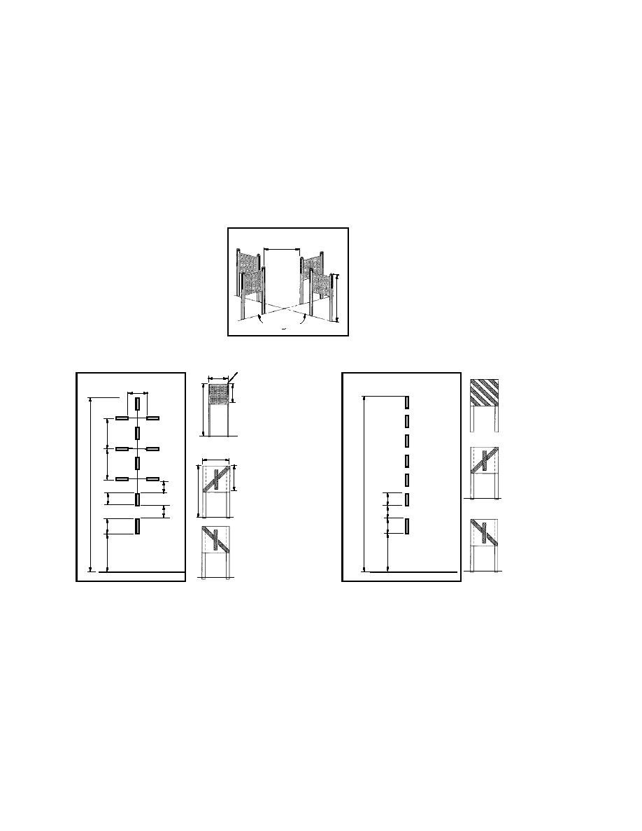
The Pegasus runway layout is shown in Fig-
positions of the access roads and supporting in-
frastructure are also shown. Figure E2 gives de-
ure E1. Included are the positions of the lead-in
tails of marker sizes, shapes, and arrangements.
markers, the ground plane approach markers, and
the distance remaining boards. The approximate
"Y" Marker
Configuration
6'
6'
Snow Line
Ground Plane Approach Markers
Threshold Markers
(black plastic net)
(orange plastic net)
and "Distance Remaining" Board
and "Distance Remaining" Board
Foil
3'
Threshold
6'
3' Ground Plane Approach
Board
and Threshold Marker
6-8'
Bamboo
9'
Inboard
4'
"Distance Remaining"
9'
100'
Inboard
Board
4' "Distance Remaining"
97'
Board
3'
8'
3'
3'
3'
3'
Outboard
4'
4'
Outboard
"Distance Remaining"
"Distance Remaining"
Board
Board
60'
60'
Edge of Runway
Edge of Runway
Figure E1. Layout of Pegasus runway and lead-in markers.
121


 Previous Page
