The dimensions of the structure considered for the present simulation is shown in the cross
section in Figure C1. The height of the structure considered was 10 feet above the ground while
the total length in the case of the model was 11 feet. Also from the boundary condition point of
view the support condition was considered to be similar to that of a cantilever beam type. This
type of support condition has been considered for the initial simulations purposes only as it
represents the worst-case scenario. However, as can be seen in the installation procedure in
Figure C1 the actual boundary condition subjects far greater constraint on the structure than
achieved by this assumption. The table gives the material properties of the PVC considered for
the present case.
Modulus of Elasticity
380,000 psi
Tensile Strength
6300 psi (<5% Total Strain)
Static Elastic Finite Element Analysis
Static linear elastic finite element analysis
of the structure was carried out using the
ANSYS FEM software. To model this
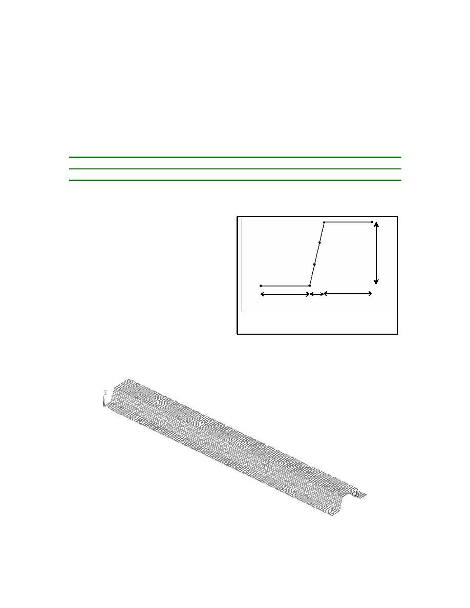
6.5"
structure for the purpose of the Finite Element
Analysis (FEA) the structure was simplified.
As shown in Figure C4 the web and flange
were modeled using the Elastic SHELL 63
2"
5"
5"
elements of thickness 0.25". The length of
structure as pointed out earlier was 11 feet.
Fig. C3 Schematic of cross section of the
The Rib and the corner stiffeners were
seawall structure used in the FEM model
modeled using the Elastic BEAM 3 elements
of diameter 0.5", cross section area of 0.196 sq in and area moment of inertia of 0.0031 in4. Also
the connecting `C' joints were modeled as the beam element, which can be further, refined to
model the exact geometry of the structure.
Figure C4. The meshing scheme adopted in the present analysis.
74


 Previous Page
