APPENDIX C. SEAWALL STRUCTURE SIMULATION RESULTS
By Uday Vaidya, University of Alabama at Birmingham
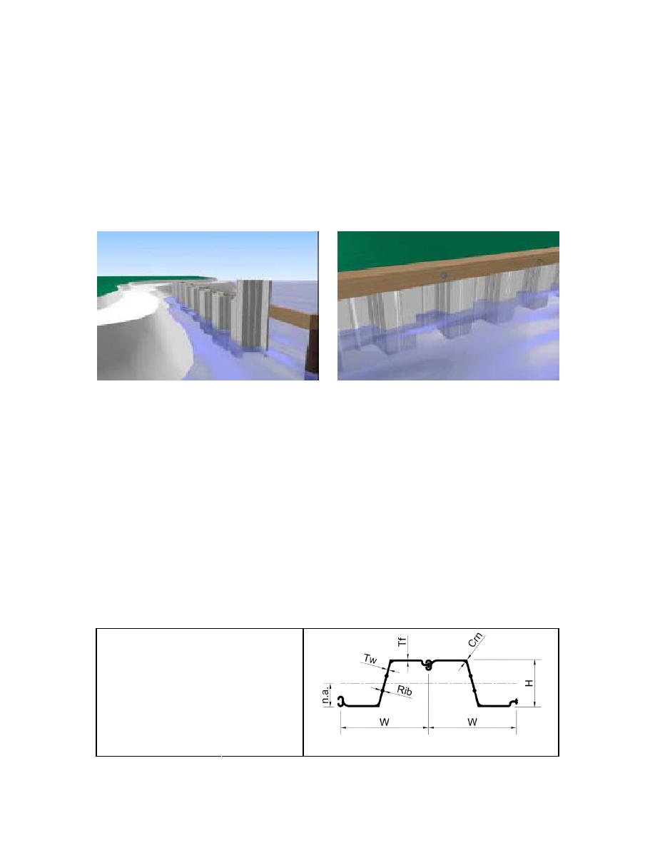
Figure C1 shows a brief demonstration of the installation procedure for a Northstar Vinyl
Seawall. The complete structure is erected using individual units of the modular structure as
shown in the Figure C2. The individual units are 12" wide. The dimensions mentioned are those
for the product series 3100c. These structures are made from the high impact and UV stabilized
Vinyl Compound, mono-extruded from pellets or regrind PVC.
Figure C1. Typical installation of the seawall structures.
According to the specification by the Northstar to provide adequate shear strength, resistance
to web crippling, and drivability during installation, the profile shall have the following geometric
properties:
Ribs- two within the web of the profile having the mentioned diameter.
Rib spacing shall be approximately one-third increments along the length of the web.
Corners (intersection between web and flange) alternate interior angles of the profile
shall be 95-110. Also, corner thickness shall be at least 50% greater than the nominal
wall thickness.
If profile does not have ribs or thickened corners, profiles average minimum thickness
shall be at least the wall thickness noted above multiplied by 1.5.
Profiles with ribs/knobs protruding from the flanges will not be allowed.
Feature
Dimension (in.)
Width (W)
12
Depth (H)
6.5
Webb Thickness (Tw)
0.25
Flange Thickness (Tf)
0.25
Corner Thickness (Crn)
0.5
Rib Diameter (Rib)
0.5
Neutral Axis (n.a.)
3.25
Flange Length
5
Figure C2. Cross section of the seawall structure.
73


 Previous Page
