Water Main
Power Cables
Concrete
8 ft
Sewer Main
Sand Pad
Clay Trough
(varies)
Non-heaving Soil
10 ft
4-in. Polyurethane
Top
12 in.
Steel
Jacket
3-in. PVC
2.5-in. PVC
Water Main
Vacuum Sewer
1-in. Copper
Wood Beam and Supports
Heat Trace Pipe
as Required
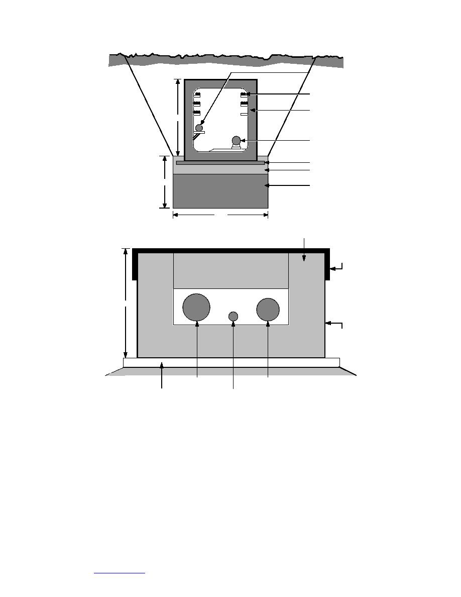
Figure 1. Cross sections of two utilidors constructed in the Arctic. (After U.S. Army 1987.)
Utilidor sizes and shapes are determined by considering the number and sizes
of the pipes they will contain, their location relative to the ground surface, and the
ease of access desired for maintenance or repairs. Phetteplace et al. (1981) presented
the utilidor and pipe sizes for all the utilidors located on Fort Wainwright, Alaska.
They reported approximately 200 different configurations; utilidor sizes ranged
from 1 ft 1 ft to 7 ft 9 ft, and pipe sizes varied from 1 in. to 24 in. in diameter.
Clearly, it is not possible to conduct physical experiments using every combina-
tion of utilidor size and pipe combination.
The objective of this work was to investigate convection and radiation in enclo-
sures, specifically rectangular utilidors containing one or more heated pipes. The
work presented considers the steady-state, two-dimensional problem of convec-
2
Go to Contents


 Previous Page
