90
HP
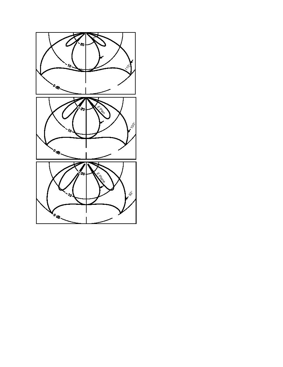
The effective transmitreceive directivities for
lan
Pl
e
a theoretical model of our radar antennas (Arcone
an
e
1995) are shown in Figure 2. These patterns are
the far field radar response to a point target that is
49
isotropic, polarization insensitive, non-disper-
sive and located in three different media. The
dielectric constants ε of the media are 1.9, an
approximate value (e.g., Cumming 1952) for the
upper layer snow at South Pole Station, 2.7
180
(dense snow) and 3.2 (ice). The patterns are more
ρ = 1.9
ε
Snow, two-way
2
directive than those of a single antenna because
= 0.5
2-cm dipoles
of the multiplication of the identical transmit and
90
HP
receive directivity patterns. The patterns were
lan
e
computed for an antenna length of 22 cm, excited
by a 2.5-ns (400-MHz) current pulse that progres-
e
sively attenuates along the length of the antenna.
44
The patterns are similar for the virtually identical,
but larger, 100-MHz antennas.
The two-way directivity in the plane of the
electric field (E-plane, which is the vertical plane
containing the antenna and perpendicular to the
180
ρ = 2.5
ε
ground surface), shows a main lobe and two
Snow, two-way
2
= 0.7
2-cm dipoles
weaker sidelobes. In snow of density 0.5 g/cm3,
the main lobe has a 3-dB beamwidth of 49 and
90
HP
lan
the sidelobes are 5 dB weaker than the main lobe
e
peak. Therefore, at a depth of about 5 m, the later-
al coverage or "footprint" is determined by the
main lobe and is about 4.6 m wide. The line spac-
43
ing for the tunnel route survey averaged 2.8 m so
that overlapping coverage was obtained. The un-
orthodox magnetic field plane (H-plane, which is
the vertical plane perpendicular to the E-plane
and the ground surface) pattern has two scal-
180
ρ = 3.2
ε
2ce, two-way
I
loped lobes whose peaks are about 9 dB above the
= 0.92
2-cm dipoles
peak E-plane intensity. An effective H-plane
Figure 2. Radar transmitreceive two-way directivity
beamwidth is not simply characterized, but using
the peak values in the 40 direction as a reference,
pattern for a finite size dipole operating over snow of dif-
ferent densities ρ and their corresponding dielectric con-
the 3-dB width of each lobe is approximately 10.
This causes signal intensity to vary strongly
which is perpendicular to the direction of surveying. The 3-
along diffraction patterns generated when pass-
dB angular width in the E-plane gives an approximate base
ing over discrete objects because profiling was
for calculating the antenna swath of sensitivity.
done along the H-plane direction. This variation
generates "noise" during migration. Migration is
patterns for point dipoles have been discussed by
a signal processing procedure used for resolving
Annan et al. (1975) and Engheta et al. (1982). This
diffractions to improve the spatial imaging of the
theory shows the radiation to be directive with
radar data. It is used later and discussed below.
deep nulls and sharp lobes in planes parallel and
perpendicular, respectively, to the antenna axis.
FIELD PROCEDURES AND
These features occur in the angular directions ψ =
DATA PROCESSING
sin1 (1/n) measured from vertical, where n is
the real part of the refractive index of the ground
Field procedures
medium. For solid ice, n = 1.78 and |ψ| = 34.
We established transects over facilities near
This angle steadily increases to a value of 46.5 for
South Pole Station by placing orange plywood
snow of n = 1.38 (density 0.5; Cumming 1952).
diamonds in the snow at set intervals along lines
3


 Previous Page
