Steel Plate (with
countersink screws)
85 cm
42.5 cm
Top View
75-L Plastic
or Nonmetallic
40 cm
Container
Drill
75-L Plastic
or Nonmetallic
Container
Stirrer
125 cm
23.5 cm
10 cm
13 cm
30 cm
Gate for
Part II
Geotextile
Tests
Aluminum Gutter
8% Grade
Wooden Block
75-L Plastic
75-L Plastic
or Nonmetallic
or Nonmetallic
Container
Container
95 cm
Front View
Side View
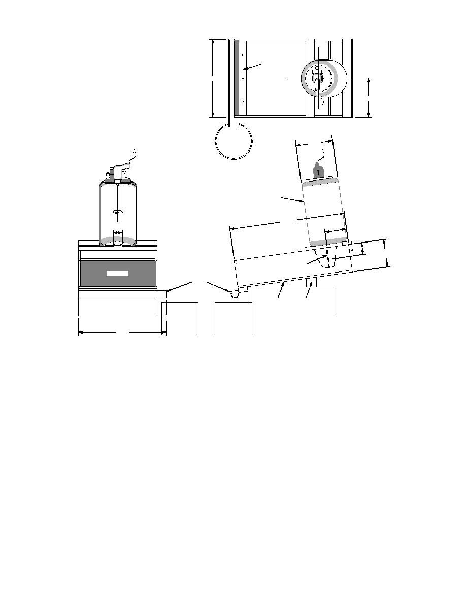
Figure 4. Diagram of flume used to conduct silt fence tests.
2) The soilwater mixture was released into
available from Forestry Suppliers, Inc., Jackson,
the flume immediately after one minute of
Mississippi.
agitation (i.e., agitation was not continued
during the release).
Part I
3) Rather than taking one depth-integrated
Twelve tests were conducted in Part I; there
sample, three samples of soil-laden water
were three replications for each of four geotextiles,
using a PVC Coliwasa water sampler were
tested in random order. The initial TSS of the sedi-
taken and analyzed independently for TSS.
ment-laden water released to the flume was ei-
Each sample was approximately 50 mL.
ther 2830 mg/L or 2880 mg/L, depending on how
In test 2, the back of the geotextile was scraped
much rinse water was used after the mixture was
with a spoon about 15 minutes after the test was
released. The procedure described in ASTM D 5141
begun and a significant increase in the instanta-
(1992) was followed, with three minor adjust-
neous flow rate of water through the geotextile
ments, listed below:
was noted. This procedure probably resulted in
1) In order to break apart aggregated soil par-
an increased amount of sediment passing through
ticles, the soil was mixed in a blender with
the geotextile and is discussed further in a later
500 mL of water before being added to the
section.
rest of the water.
4


 Previous Page
