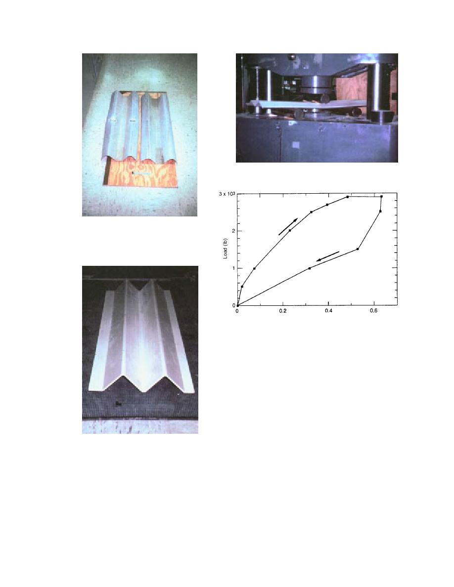
Figure 11. Testing of commercial FRP beam W-
configuration.
Figure 9. Tested (left) and untested
(right) AASHTO W-beams. Note the
local "yielding" as the energy absorp-
tion mechanism in these beams.
Deflection (in.)
Figure 12. Test results of commercial FRP beam of W-
configuration.
the loading and unloading curve gives the energy
absorbed in the fracture process.
The key to developing a large amount of
energy absorption is to design the composite
W-beam with constituents arranged in such a
manner that progressive crushing occurs. The
crash would be expected to move at approxi-
mately a constant load equal to the residual load
and also at the velocity dictated by the decelera-
tion rate of the errant vehicle. The aim here is to
achieve extensive microfracturing of the matrix
Figure 10. Commercially available pul-
and partial failure of the fibers by breakage and
truded FRP section of W-configuration,
pullout, so that sufficient residual load is sus-
used for initial test (layup unknown).
tained to guide the errant vehicle back to its pre-
vious course.
W-beam, loading was applied in a three-point
bending test configuration (Fig. 11) and load-
FRP W-beam design approach
deflection characteristics were recorded (Fig. 12).
The initial tests showed that the FRP compos-
Note that the beam rebounded after the load was
ites will have a low stiffness and will be highly
removed. Energy was absorbed by a fracture that
resilient, despite brittle fracture. Before a compos-
developed at the loading point. The area between
ite W-beam was designed, a detailed review of the
12


 Previous Page
