CHAPTER 2: BACKGROUND
Roadside safety hardware (barriers, crash cush-
and along its length. Thus, a good composite's
ions, signs and light supports, etc.) must perform
performance essentially depends on the interfa-
important safety functions to the errant, out-of-
cial bond quality. When a load is applied in the
control vehicles, and yet must have low installa-
direction of the fiber orientation of the compos-
tion and maintenance costs. Metals (steel and
ite, the load is shared both by the fiber and the
aluminum) and concrete have been the most com-
polymer matrix. The ratio of this load distribution
mon materials for these structures. However, over
depends on the relative elastic modulus of the
the past three decades, the engineering use of
fiber and the matrix (Chamis 1974). However, the
fiber reinforced plastics (FRP) composites has pro-
elastic modulus of the polymer matrix is signifi-
liferated, and FHWA has been actively examining
cantly influenced by the temperature. At lower
these materials for various highway uses, includ-
temperature, the modulus of elasticity increases
ing the roadside safety structures. The Agency has
considerably, and thus the load distribution
supported important studies of the impact behav-
between the fibers and the matrix changes. In its
ior of the FRP composites produced in the
simplest form, the polymer composite material
pultruded form (Svenson et al. 1993), investigated
can be visualized as a bundle of solid rods held
the durability of FRP rebars for concrete (Ander-
together with a glue, filling up all the void space
son et al. 1994), and sponsored a bold new initia-
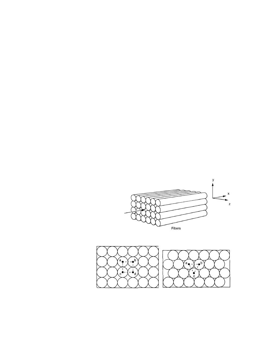
around the fibers (see Fig. 1). However, in the
tive in design developments for all-composite
microscopic scale, these solid rods have a diam-
vehicular bridges (Seible 1996). A summarized
eter varying in the range of 5 microns for carbon
version of the current research effort of this
fibers, to about 20 microns for glass fibers (one
micron = 1 m). It is interesting to note how these
report and the program goals of the applications
of FRP and RPC in highway safety structures has
fibers are packed together. Figure 2a shows a
been reported earlier (Dutta and McDevitt 1994,
square array packing when the fibers lie on top of
McDevitt and Dutta 1993).
each other. Under this packing condition, the void
To the general engineering community, FRP is
volume is greater than the void volume in the hex-
a complex and unfamiliar engineering structural
agonal array of packing shown in Figure 2b. The
material. It is perceived by many as an aero-
space material and, therefore, would be expen-
sive to produce, design with, and use. The sec-
tions of this chapter are therefore devoted to
describing this material, referred to either as
FRP composite or FRP.
Fiber reinforced polymer (FRP)
composites
In polymer composites, high elastic modu-
lus fibers are incorporated into a lower elastic
modulus matrix to achieve structural rein- Figure 1. Representation of fiber composites as a bundle of
forcement. Most common fibers are E-glass, solid rods.
carbon or graphite, and ara-
mids (Kevlar). Typically the
elastic modulus and strength
of these fibers are a mag-
nitude higher than those
properties of the polymer
matrix in which the fibers
are embedded. The essential
quality of a good composite
is that the bond between the
a. Square array (fiber volume frac- b. Hexagonal array (fiber volume frac-
fiber and the matrix is well
tion: 90.7%).
tion: 78.5%).
established and is continu-
Figure 2. General arrangements (packing) of fibers.
ous both around the fiber
3


 Previous Page
